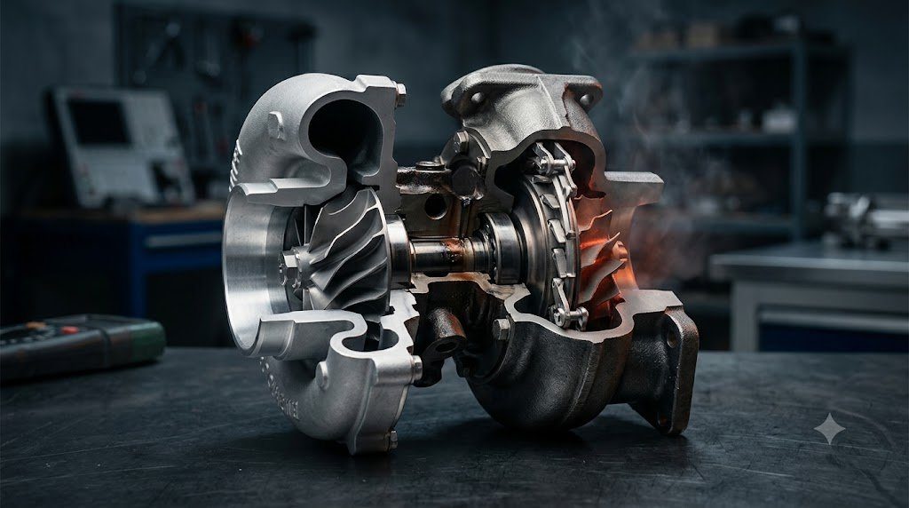
Forced induction turbocharging is the primary engineering catalyst behind modern engine downsizing, enabling modest 1.5 to 2.0-liter displacement powerplants to produce torque curves that surpass large naturally aspirated V8 engines. By capturing thermal enthalpy and kinetic momentum that would otherwise be rejected into the atmosphere via the exhaust pipe, a turbocharger drives a centrifugal compressor to pack dense, high-mass air into the engine cylinders, raising Indicated Mean Effective Pressure (IMEP) and overall powertrain efficiency.
In an internal combustion engine, approximately 30% to 35% of the total fuel energy is lost directly through exhaust thermal enthalpy. A turbocharger functions as an enthalpy recovery turbine: hot exhaust gases expand through the turbine volute, converting gas pressure and temperature drop ($\Delta h = C_p \Delta T$) into rotational shaft power ($P_{shaft} = \dot{m}_{ex} \Delta h_{turb} \eta_{turb}$) spinning the common shaft at speeds exceeding 150,000 to 250,000 RPM.
Centrifugal Compressor Thermodynamics: Pressure Ratio and Mass Flow
The performance of a turbocharger compressor is mathematically mapped on a two-dimensional plot displaying the Total-to-Total Pressure Ratio ($\Pi_c = P_{02} / P_{01}$) against Corrected Mass Airflow ($\dot{m}_{corr}$). As ambient air enters the spinning impeller eye, curved vanes impart high angular velocity to the fluid. The air then passes through a stationary vaned or vaneless diffuser ring, where kinetic dynamic velocity is converted into static pressure via Bernoulli’s principle.
The compressor operating map is delineated by two critical aerodynamic boundaries:
- The Surge Line (Left Boundary): Occurs when airflow is too low for a given pressure ratio, causing aerodynamic boundary layer stall across the compressor impeller blades. Air flow violently reverses direction, oscillating backward through the compressor with loud fluttering noises, creating extreme axial thrust loads that destroy turbocharger journal and thrust bearings within seconds.
- The Choke Line (Right Boundary): Occurs when gas velocity through the compressor inlet throat reaches the local speed of sound (Mach 1.0). Once sonic choking occurs, mass airflow reaches an absolute physical ceiling, and compressor isentropic efficiency plunges precipitously below 55%, dumping massive frictional heat into the charge air.
Turbine Expansion Aerodynamics: A/R Ratio and Pulse Energy
The turbine housing is designed around its fundamental geometric parameter: the Area-to-Radius (A/R) Ratio. The cross-sectional inlet area ($A$) of the scroll divided by the distance ($R$) from the center of that area to the turbine shaft axis dictates exhaust gas velocity directed into the turbine wheel blades:
- Small A/R Ratio (e.g., 0.48 – 0.60): Accelerates exhaust gas to high velocity even at low engine RPM, delivering rapid boost response and minimizing ‘turbo lag’. However, at high engine RPM, the small scroll presents excessive exhaust backpressure, choking cylinder scavenging and increasing pumping losses.
- Large A/R Ratio (e.g., 0.82 – 1.06): Reduces exhaust backpressure at high RPM, allowing maximum horsepower. However, at low exhaust flow rates, gas velocity is insufficient to spin the turbine quickly, resulting in noticeable turbo lag.
| Turbocharging Technology | Boost Regulation Mechanism | Low-RPM Spool Response | High-RPM Backpressure | Typical Temperature Limit |
|---|---|---|---|---|
| Internal Wastegate Turbo | Pneumatic/Electric Bypass Flapper | Moderate Spool | Moderate Backpressure | Up to 950°C (Gasoline) |
| Variable Geometry Turbine (VGT) | Pivoting Aerodynamic Nozzle Vanes | Extremely Rapid (No Wastegate) | Low Backpressure across Range | Up to 850°C (Standard) / 1000°C (High-Alloy) |
| Twin-Scroll Turbo | Divided Exhaust Scroll (1-4 & 2-3) | Rapid Spool (Pulse Energy) | Low Pumping Loss | Up to 980°C (Gasoline) |
| Electric Assist Turbo (e-Turbo) | 48V High-Speed Motor on Shaft | Instantaneous (Zero Lag) | Optimized across All Speeds | Up to 1050°C (Motorsport) |
Variable Geometry Turbines (VGT) and Electric Wastegate Actuators
To eliminate the historical compromise of fixed A/R turbine housings, Variable Geometry Turbines (VGT / VNT) incorporate an array of aerodynamically profiled guide vanes arrayed around the turbine wheel circumference. At low engine speeds, an electric stepper motor angles the vanes toward a closed position, creating narrow convergent nozzles that accelerate low exhaust flow into high-velocity gas jets that spin the turbine rapidly.
At high engine speeds, the vanes pivot wide open, expanding the effective nozzle area to prevent excessive manifold backpressure. While long ubiquitous in diesel applications due to lower exhaust gas temperatures (~750°C to 800°C), modern gasoline engines now utilize advanced nickel-chromium superalloys (such as Inconel 713C and titanium-aluminum alloys) to deploy VGT mechanisms in extreme 1,000°C gasoline exhaust streams.
Charge Air Cooling (Intercooling) and Thermal Density Gains
When a compressor elevates manifold pressure to 1.5 or 2.0 bar gauge (21 to 29 psi), isentropic gas compression inevitably heats the air charge to 140°C to 180°C. Air at elevated temperatures suffers from low molecular density and drastically promotes destructive cylinder knock.
An Intercooler (Charge Air Cooler)—either air-to-air or liquid-to-air—cools the compressed air back down to within 10°C to 15°C of ambient temperature. According to the ideal gas law ($P = \rho R T$), cooling the charge at constant boost pressure increases air density ($\rho$) proportionally, packing significantly more oxygen molecules into the cylinder for each combustion stroke while simultaneously protecting the piston crown from thermal fatigue.
Compressor Blade High-Cycle Fatigue (HCF) and Aerodynamic Blade Flutter
The forged milled aluminum compressor wheel of a modern automotive turbocharger operates under extreme centrifugal tensile stress fields generated by tip speeds exceeding Mach 1.5 to 1.8 (450 to 550 m/s). However, the most destructive mechanical failure mode is not centrifugal burst; it is High-Cycle Aerodynamic Fatigue (HCF).
As compressor blades rotate past stationary casting struts or intake plumbing bends, periodic aerodynamic pressure pulses strike the leading edges. If these excitation frequencies match the blade’s natural resonant vibration modes (evaluated via Campbell Diagrams), the blades experience violent flutter oscillations exceeding the material’s fatigue endurance limit ($S_e$), causing blade tip corners to fracture and eject into the compressor housing with catastrophic shrapnel release.
Full-Floating vs. Semi-Floating Journal Bearing Hydrodynamics
To survive shaft speeds exceeding 200,000 RPM, turbocharger center rotating assemblies utilize Full-Floating Bronze Journal Bearings running with dual oil clearance films: an inner oil film between shaft and bearing bore, and an outer oil film between bearing OD and the center housing. The bearing itself rotates at approximately one-third of shaft speed, halving relative sliding velocity and providing dual squeeze-film hydrodynamic damping that suppresses destructive sub-synchronous oil whirl instability.
Field Case Study: Hot Shutdown Carbonization and Turbocharger Oil Coking
When an internal combustion engine is operated under heavy boost, the turbocharger turbine housing and center bearing housing reach scalding temperatures between 650°C and 950°C. In older turbocharged engines without auxiliary cooling systems, shutting the engine off immediately after hard driving—a phenomenon termed Hot Shutdown—cuts engine oil pressure and flow instantly.
Stationary motor oil trapped within the superheated center bearing housing boils and carbonizes, forming abrasive solid carbon grit—termed Oil Coking. Upon the next engine start, this abrasive carbon grit scores shaft journal surfaces, blocks precision oil feed holes, and causes bearing seizure within 5,000 kilometers.
Electric Auxiliary After-Run Coolant Pumps and Thermosyphon Loops
Modern turbocharged powertrains completely eliminate oil coking through two engineering innovations: water-cooled center bearing housings and Electric Auxiliary Coolant Pumps. When the ignition is turned off, the ECU commands the electric auxiliary pump to circulate coolant backward through the turbocharger for up to 10 minutes. Furthermore, the bearing housing coolant ports are angled to induce natural Thermosyphon Circulation: boiling coolant rises, pulling cool water through the engine block via natural convection even if electrical power fails.
Standardized Workshop Inspection Protocols and Factory Assembly Tolerances
Professional automotive service and certified powertrain remanufacturing adhere strictly to standardized workshop procedures defined by the Society of Automotive Engineers (SAE International), the International Organization for Standardization (ISO), and OEM factory workshop manuals. Rebuilding modern vehicle subsystems requires rigorous mechanical measuring tools, calibrated digital torque-to-yield angle meters, and ultra-clean workshop assembly cleanrooms.
When assembling high-precision automotive components—such as crankshaft main journal bearings, transmission planetary carriers, high-pressure fuel injectors, or multi-piston brake calipers—technicians enforce strict cleanliness standards governed by ISO 16232 (Road Vehicles – Cleanliness of Components and Systems). Component parts must be washed in ultrasonic cleaning tanks using solvent degreasers, dried with filtered compressed air, and inspected under particulate optical microscopes to verify that residual metallic particles do not exceed 200 micrometers.
Torque-to-Yield (TTY) Fasteners and Ultrasonic Bolt Tension Measurement
Critical powertrain and chassis joints—such as cylinder head bolts, connecting rod cap bolts, flywheel bolts, and suspension knuckle fasteners—universally utilize Torque-to-Yield (TTY) Fasteners. Unlike standard elastic bolts that operate within their linear elastic region, TTY bolts are tightened past their proportional limit into plastic deformation, providing constant clamp load despite thermal expansion cycles.
Technicians must utilize calibrated digital torque-angle wrenches: the fastener is first tightened to a specified initial snug torque (e.g., 40 Nm), followed by one or two precise rotational angle sweeps (e.g., +90° +90°). Because TTY fasteners undergo permanent plastic elongation, they are strictly single-use components; reusing a stretched TTY fastener risks catastrophic bolt necking and fastener shear under high cylinder pressure.
Comprehensive Workshop Maintenance and Tolerance Inspection Matrix
| Inspection Parameter / Task | Governing Standard / Tool | Allowable Workshop Tolerance | Critical Diagnostic Action Required |
|---|---|---|---|
| Bearing & Journal Clearances | Plastigage / Precision Micrometers | 0.025 to 0.050 mm (0.0010 – 0.0020 in) | Select undersize/oversize selective bearings |
| Cylinder Bore Taper & Out-of-Round | Dial Bore Gauge (Three Axis) | < 0.012 mm (0.0005 in) Maximum | Precision CNC plateau hone or overbore sleeve |
| Brake Rotor Lateral Runout | Dial Indicator on Magnetic Base | < 0.038 mm (0.0015 in) Assembled | Index rotor on hub or machine with on-car lathe |
| Wheel Hub Bearing Endplay | Dial Indicator Axial Deflection | < 0.050 mm (0.0020 in) Axial Play | Replace integrated hub bearing unit if exceeded |
| CAN Bus Static Resistance | Digital Multimeter (Pins 6 & 14) | 59.0 to 61.5 Ohms Balanced | Inspect 120-ohm terminating resistors & splices |
Adherence to these rigorous dimensional tolerances, factory torque tightening angles, and certified testing standards guarantees that serviced vehicle subsystems operate with original equipment factory reliability, thermal endurance, and maximum occupant safety throughout their operational lifecycle.
International Engineering Standards, Regulatory Audits and Quality Compliance
The engineering validation, roadworthiness certification, and manufacturing quality of motor vehicles are governed by stringent international regulatory treaties and engineering standards. Across major global automotive markets—predominantly the United States Federal Motor Vehicle Safety Standards (FMVSS), European Union Whole Vehicle Type Approval (EU WVTA / UNECE Regulations), and ISO 26262 Road Vehicles Functional Safety—every powertrain, chassis, and electronic subsystem must prove compliance through exhaustive durability and laboratory crash tests.
ISO 26262 Automotive Safety Integrity Level (ASIL) Classifications
Modern software-defined vehicles integrate safety-critical electronics under the rigorous framework of ISO 26262. Subsystems are categorized into Automotive Safety Integrity Levels ranging from ASIL-A (lowest hazard) to ASIL-D (highest safety criticality) based on three risk factors: Severity of injury ($S$), Exposure probability ($E$), and Driver Controllability ($C$):
- ASIL-D Subsystems (Zero-Tolerance Failure): Brake-by-wire modulators, Electronic Stability Control (ESC), Electric Power Steering (EPS), and High-Voltage Battery Disconnect Units (BDU). Mandates dual lockstep microcontroller cores, redundant hardware power feeds, and automated failure detection within 10 to 20 milliseconds.
- ASIL-C Subsystems: Electric traction motor torque control and transmission electronic shift-by-wire interlocks.
- ASIL-B Subsystems: Adaptive cruise control (ACC), lane departure warning, and active suspension dampening.
Global Emissions Regulatory Roadmaps: EPA Tier 3, Euro 6d and Euro 7
Internal combustion engines, direct injection fuel systems, and hybrid powertrains are subjected to continuously tightening exhaust emissions legislation. Under Euro 6d-ISC-FCM and forthcoming Euro 7 standards, vehicles must prove real-world emissions compliance on public highways using portable emissions measurement systems (PEMS) across ambient temperatures from -10°C to +38°C:
- Nitrogen Oxides ($NO_x$): Limited to less than 60 mg/km (gasoline) and 80 mg/km (diesel) through combined Selective Catalytic Reduction (SCR) with AdBlue urea injection and cooled low-pressure EGR loops.
- Solid Particle Number ($PN_{10}$): The regulatory measurement threshold has been tightened from 23 nanometers down to 10 nanometers, mandating wall-flow Gasoline Particulate Filters (GPF) across all turbocharged GDI engines.
- On-Board Fuel Consumption Monitoring (OBFCM): Standardized telemetry logging real-world lifetime fuel and electrical energy consumption directly within the engine ECU for regulatory transparency.
By anchoring design methodologies to these internationally recognized SAE, ISO, and UNECE standards, automotive engineers and diagnostic practitioners ensure that mechanical components deliver peak operational reliability, environmental compliance, and life-saving occupant protection.
Combustion Chamber Fluid Mechanics, Tumble Flow and Thermodynamic Boundary Layers
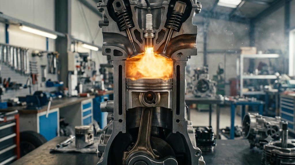
In the thermodynamic optimization of internal combustion engines, the geometric architecture of the cylinder head combustion roof exerts direct control over flame propagation speed and thermal heat losses. Modern direct-injection four-valve pent-roof combustion chambers are engineered to generate high-velocity Intake Tumble Flow—a coherent barrel-shaped vortex of air rotating perpendicularly to the cylinder axis.
As the piston accelerates upward on the compression stroke toward Top Dead Center, geometric squish pads on the piston crown compress this large tumble vortex, breaking it down into a cascade of fine, high-intensity microscopic turbulent eddies. This microscopic turbulence increases the Turbulent Flame Speed ($u_t$) by a factor of four compared to laminar flame speeds ($u_l$), completing combustion in fewer crank angle degrees and allowing significant spark retard reduction.
Piston Ring Tribology and Blow-by Hermetic Gas Sealing
Reciprocating pistons rely on three precision-engineered piston rings running inside plateau-honed cylinder liners to maintain gas hermetic sealing while controlling oil consumption: the Top Compression Ring, the Second Scraper Ring, and the Three-Piece Oil Control Ring. The top compression ring—manufactured from nodular cast iron or stainless steel with physical vapor deposition (PVD) diamond-like carbon (DLC) coatings—utilizes cylinder gas combustion pressure entering behind the ring groove to force the ring face tightly against the cylinder wall. Minimizing blow-by past the ring gaps to under 15 to 25 liters per minute prevents crankcase pressurization, preserves oil quality, and eliminates hydrocarbon emissions leakage.

Lead Automotive Research Engineer, Master ASE Certified Diagnostic Specialist, and powertrain dynamics consultant with over 18 years of experience in internal combustion thermodynamics, electric vehicle architectures, and chassis control systems.