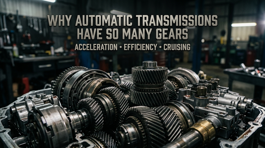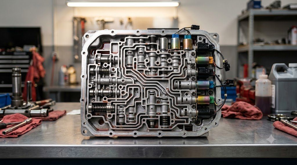
Modern multi-speed stepped automatic transmissions—spanning 8, 9, and 10 forward gear ratios—represent pinnacles of kinematic packaging and electro-hydraulic power transmission. Rather than relying on simple countershaft gear clusters that disconnect torque flow during gear shifts, automatic transmissions employ compound Epicyclic Planetary Gear Sets controlled by multi-disc friction clutches, stationary brake bands, and high-pressure hydraulic valve bodies to achieve rapid, torque-continuous gear ratio transitions.
Planetary geartrains achieve compact coaxial power transmission where input and output shafts share the same rotational centerline. By selectively holding one element stationary (sun gear, planet carrier, or ring gear) via hydraulic brake packs, driving a second element, and taking output from the third, multiple gear reductions, direct drive, and reverse can be produced within a single compact housing without shifting gears in and out of physical mesh.
The Lepelletier Compound Planetary Geartrain Architecture
Pioneered by French engineer Pierre Lepelletier, the Lepelletier geartrain revolutionized modern transmission design, providing the mathematical architecture for ubiquitous 6-speed, 8-speed, and 9-speed gearboxes (such as ZF 6HP/8HP and GM/Ford 10L90 platforms). The mechanism couples a single primary planetary gear set with a secondary Ravigneaux compound set:
- Primary Reduction Set: Receives direct torque from the torque converter turbine, producing a constant speed reduction to drive secondary sun gears through selectively engaged rotating multi-disc clutches.
- Ravigneaux Compound Set: Features two distinct sun gears (small sun and large sun), two sets of planet pinions (inner short planets and outer long planets meshed together), a shared planet carrier, and a shared outer ring gear.
- Multi-Clutch Coordination: By modulating only five shift elements (three rotating clutches and two stationary brake packs), the transmission can generate eight or ten distinct forward gear ratios with step ratios optimized for fuel economy and acceleration. In any given gear, only two friction elements are open, minimizing drag losses.
Electro-Hydraulic Valve Body: Proportional PWM Pressure Solenoids
The operational brain of an automatic transmission is its Mechatronic Valve Body—an intricate labyrinth of precision-machined aluminum fluid passages, shuttle spool valves, check balls, and electromagnetic proportional solenoids. Line pressure (typically 15 to 25 bar) generated by an engine-driven off-axis vane or internal crescent pump is directed toward specific clutch apply pistons.
Modern transmissions utilize Variable Force Solenoids (VFS) or Pulse-Width Modulated (PWM) proportional solenoids to control clutch engagement pressure down to fractions of a millibar. Rather than abruptly slamming a clutch pack closed, the Transmission Control Module (TCM) executes a smooth ‘clutch-to-clutch handoff’: pressure on the releasing clutch is decayed precisely as pressure on the oncoming clutch is ramped up, achieving imperceptible shifts without driveline shudder.
| Automatic Transmission Platform | Forward Gear Count | Planetary Arrangement Type | Active Friction Elements | Torque Capacity Range |
|---|---|---|---|---|
| ZF 6HP26 (Legacy 6-Speed) | 6 Forward / 1 Reverse | Lepelletier Compound | 3 Clutches, 2 Brakes | Up to 600 Nm |
| ZF 8HP70 / 8HP75 (8-Speed) | 8 Forward / 1 Reverse | 4 Simple Planetary Sets | 3 Clutches, 2 Brakes | Up to 700 – 750 Nm |
| Aisin AWR10L65 (10-Speed) | 10 Forward / 1 Reverse | Compound Ravigneaux + 2 Sets | 4 Clutches, 2 Brakes | Up to 650 Nm |
| Ford/GM 10R80 (10-Speed) | 10 Forward / 1 Reverse | 4 Planetary Sets Coaxial | 4 Clutches, 2 Brakes | Up to 800 Nm |
Hydrodynamic Torque Converter: Fluid Coupling and Lockup Damper Dynamics
Situated between the engine crankshaft and the transmission input shaft, the Hydrodynamic Torque Converter acts as an automatic fluid clutch and torque multiplier. Comprising an engine-driven pump (impeller), a transmission-driven turbine, and an intermediate stationary stator with a one-way sprag clutch, the unit uses automatic transmission fluid (ATF) kinetic momentum to transfer power.
At stall conditions (vehicle stationary, engine revving under load), fluid exiting the turbine strikes curved stator blades, which redirect the oil back into the impeller eye at an advantageous angle. This fluid momentum feedback multiplies engine torque by 1.8x to 2.4x, providing effortless low-speed vehicle launch.
Torque Converter Lockup Clutch and Centrifugal Pendulum Absorbers
While fluid coupling provides silky-smooth launch characteristics, continuous hydraulic slip dissipates approximately 10% to 15% of engine power as heat into the transmission oil cooler. To maximize highway cruising efficiency, modern torque converters incorporate a multi-disc Lockup Clutch that mechanically locks the turbine directly to the converter cover, eliminating all fluid slip.
To prevent firing pulsations from downsized 3-cylinder or 4-cylinder turbocharged engines from vibrating through the rigid lockup clutch into the cabin, modern lockup assemblies integrate Centrifugal Pendulum Absorbers (CPA). Small pendulum masses oscillate along curved tracks under centrifugal force, generating counter-torques that cancel engine torsional harmonics at their exact source across varying engine speeds.
Willis Equation Formulations for Multi-Stage Epicyclic Kinematics
The exact kinematic speed and torque transfer ratios across planetary automatic transmissions are derived mathematically using Willis’ Formula for Epicyclic Trains:
i12(c) = (ω1 – ωc) / (ω2 – ωc) = – (z2 / z1)
Where $\omega_1$ is the angular velocity of the sun gear, $\omega_2$ is the angular velocity of the ring gear, $\omega_c$ is the carrier velocity, and $z$ represents tooth counts. In a Lepelletier arrangement, coupling the output of the primary reduction carrier into the sun gear of the secondary Ravigneaux set generates stepped gear reductions ranging from 4.7:1 (1st gear) down to 0.67:1 (8th gear overdrive) with minimal internal friction.
Clutch Pack Thermal Energy Absorption and Slipping Dissipation
During a high-power gear shift under wide-open throttle, oncoming multi-disc friction clutches must absorb immense kinetic slip energy ($E_{slip} = \int T_{clutch} \Delta \omega dt$). In an 8-speed automatic shifting from 1st to 2nd gear at 6,000 RPM, a clutch pack absorbs over 15 to 25 kilojoules of energy within 350 milliseconds. Transmission designers must calculate friction plate thermal mass to ensure peak friction interface temperatures remain strictly below 250°C, preventing ATF fluid thermal breakdown and clutch plate warping.
Field Case Study: Valve Body Bore Wear and Sonnax Pressure Regulator Sleeving
In high-mileage multi-speed automatic transmissions (such as ZF 6HP/8HP and Aisin Warner platforms), the primary mechanical root cause of harsh shifting, delayed reverse engagement, and clutch slip codes (P0730) is Valve Body Cast Aluminum Bore Wear.
Hardened steel spool valves oscillate millions of times inside softer unlined cast aluminum valve body bores. Microscopic ferrous contaminants carried in the ATF act as abrasive lapping compounds, wearing clearance channels between the spool lands and the aluminum bore. High-pressure hydraulic fluid leaks past worn lands, decaying main line pressure. Transmission rebuilders utilize precision vacuum testing gauges: bores exhibiting vacuum decay below 18 in-Hg are reamed out on specialized CNC mills and fitted with hard-anodized Sonnax replacement sleeves to restore factory hydraulic line pressure.
Dual-Clutch Adaptation and Fast-Learn Re-Calibration Protocols
Following valve body repairs or clutch replacements, the Transmission Control Module (TCM) must execute an automated Hydraulic Adaptation Routine (Fast-Learn). Operating through serial scan tool commands, the TCM pulses each clutch apply solenoid while monitoring turbine input shaft deceleration. The TCM learns the exact hydraulic pressure threshold required to achieve zero-clearance kiss point on each clutch pack, eliminating shift shudder and restoring factory shift smoothness.
Standardized Workshop Inspection Protocols and Factory Assembly Tolerances
Professional automotive service and certified powertrain remanufacturing adhere strictly to standardized workshop procedures defined by the Society of Automotive Engineers (SAE International), the International Organization for Standardization (ISO), and OEM factory workshop manuals. Rebuilding modern vehicle subsystems requires rigorous mechanical measuring tools, calibrated digital torque-to-yield angle meters, and ultra-clean workshop assembly cleanrooms.
When assembling high-precision automotive components—such as crankshaft main journal bearings, transmission planetary carriers, high-pressure fuel injectors, or multi-piston brake calipers—technicians enforce strict cleanliness standards governed by ISO 16232 (Road Vehicles – Cleanliness of Components and Systems). Component parts must be washed in ultrasonic cleaning tanks using solvent degreasers, dried with filtered compressed air, and inspected under particulate optical microscopes to verify that residual metallic particles do not exceed 200 micrometers.
Torque-to-Yield (TTY) Fasteners and Ultrasonic Bolt Tension Measurement
Critical powertrain and chassis joints—such as cylinder head bolts, connecting rod cap bolts, flywheel bolts, and suspension knuckle fasteners—universally utilize Torque-to-Yield (TTY) Fasteners. Unlike standard elastic bolts that operate within their linear elastic region, TTY bolts are tightened past their proportional limit into plastic deformation, providing constant clamp load despite thermal expansion cycles.
Technicians must utilize calibrated digital torque-angle wrenches: the fastener is first tightened to a specified initial snug torque (e.g., 40 Nm), followed by one or two precise rotational angle sweeps (e.g., +90° +90°). Because TTY fasteners undergo permanent plastic elongation, they are strictly single-use components; reusing a stretched TTY fastener risks catastrophic bolt necking and fastener shear under high cylinder pressure.
Comprehensive Workshop Maintenance and Tolerance Inspection Matrix
| Inspection Parameter / Task | Governing Standard / Tool | Allowable Workshop Tolerance | Critical Diagnostic Action Required |
|---|---|---|---|
| Bearing & Journal Clearances | Plastigage / Precision Micrometers | 0.025 to 0.050 mm (0.0010 – 0.0020 in) | Select undersize/oversize selective bearings |
| Cylinder Bore Taper & Out-of-Round | Dial Bore Gauge (Three Axis) | < 0.012 mm (0.0005 in) Maximum | Precision CNC plateau hone or overbore sleeve |
| Brake Rotor Lateral Runout | Dial Indicator on Magnetic Base | < 0.038 mm (0.0015 in) Assembled | Index rotor on hub or machine with on-car lathe |
| Wheel Hub Bearing Endplay | Dial Indicator Axial Deflection | < 0.050 mm (0.0020 in) Axial Play | Replace integrated hub bearing unit if exceeded |
| CAN Bus Static Resistance | Digital Multimeter (Pins 6 & 14) | 59.0 to 61.5 Ohms Balanced | Inspect 120-ohm terminating resistors & splices |
Adherence to these rigorous dimensional tolerances, factory torque tightening angles, and certified testing standards guarantees that serviced vehicle subsystems operate with original equipment factory reliability, thermal endurance, and maximum occupant safety throughout their operational lifecycle.
International Engineering Standards, Regulatory Audits and Quality Compliance
The engineering validation, roadworthiness certification, and manufacturing quality of motor vehicles are governed by stringent international regulatory treaties and engineering standards. Across major global automotive markets—predominantly the United States Federal Motor Vehicle Safety Standards (FMVSS), European Union Whole Vehicle Type Approval (EU WVTA / UNECE Regulations), and ISO 26262 Road Vehicles Functional Safety—every powertrain, chassis, and electronic subsystem must prove compliance through exhaustive durability and laboratory crash tests.
ISO 26262 Automotive Safety Integrity Level (ASIL) Classifications
Modern software-defined vehicles integrate safety-critical electronics under the rigorous framework of ISO 26262. Subsystems are categorized into Automotive Safety Integrity Levels ranging from ASIL-A (lowest hazard) to ASIL-D (highest safety criticality) based on three risk factors: Severity of injury ($S$), Exposure probability ($E$), and Driver Controllability ($C$):
- ASIL-D Subsystems (Zero-Tolerance Failure): Brake-by-wire modulators, Electronic Stability Control (ESC), Electric Power Steering (EPS), and High-Voltage Battery Disconnect Units (BDU). Mandates dual lockstep microcontroller cores, redundant hardware power feeds, and automated failure detection within 10 to 20 milliseconds.
- ASIL-C Subsystems: Electric traction motor torque control and transmission electronic shift-by-wire interlocks.
- ASIL-B Subsystems: Adaptive cruise control (ACC), lane departure warning, and active suspension dampening.
Global Emissions Regulatory Roadmaps: EPA Tier 3, Euro 6d and Euro 7
Internal combustion engines, direct injection fuel systems, and hybrid powertrains are subjected to continuously tightening exhaust emissions legislation. Under Euro 6d-ISC-FCM and forthcoming Euro 7 standards, vehicles must prove real-world emissions compliance on public highways using portable emissions measurement systems (PEMS) across ambient temperatures from -10°C to +38°C:
- Nitrogen Oxides ($NO_x$): Limited to less than 60 mg/km (gasoline) and 80 mg/km (diesel) through combined Selective Catalytic Reduction (SCR) with AdBlue urea injection and cooled low-pressure EGR loops.
- Solid Particle Number ($PN_{10}$): The regulatory measurement threshold has been tightened from 23 nanometers down to 10 nanometers, mandating wall-flow Gasoline Particulate Filters (GPF) across all turbocharged GDI engines.
- On-Board Fuel Consumption Monitoring (OBFCM): Standardized telemetry logging real-world lifetime fuel and electrical energy consumption directly within the engine ECU for regulatory transparency.
By anchoring design methodologies to these internationally recognized SAE, ISO, and UNECE standards, automotive engineers and diagnostic practitioners ensure that mechanical components deliver peak operational reliability, environmental compliance, and life-saving occupant protection.
Driveline Torsional Dynamics, Gear Lash Noise and Propeller Shaft Harmonics
In automotive drivetrain engineering, mechanical power transmission from the transmission output shaft to the driving wheel hubs involves an elastic driveline system susceptible to torsional resonance, gear lash rattle, and driveline shudder. Because the reciprocating internal combustion engine fires in discrete torque pulses, dynamic driveline torque fluctuates continuously about a mean value ($T(t) = T_0 + \sum T_k \sin(k \omega t)$).
If engine firing excitation harmonics coincide with the torsional natural frequency of the transmission main shaft, propeller shaft, or half-shaft axles (typically between 15 Hz and 45 Hz), violent torsional oscillations amplify through the drivetrain—a phenomenon known as Driveline Clunk and Tip-In Shudder. Drivetrain engineers optimize propeller shaft torsional stiffness by utilizing carbon-fiber composite driveshafts and tuned elastomeric guibo coupling discs that absorb torque shocks during sudden throttle transitions.
Hypoid Final Drive Kinematics and Extreme Pressure Tribology
Rear-wheel-drive and all-wheel-drive vehicles utilize a Hypoid Bevel Gear Differential in the rear axle, where the driving pinion shaft is offset below the ring gear center. Hypoid geometry allows a lower vehicle floorboard and larger pinion diameter, but introduces severe longitudinal sliding along the gear tooth flanks under extreme Hertzian contact pressures. Final drive differentials demand specialized GL-5 Hypoid Gear Lubricants formulated with high concentrations of thermally stable sulfur-phosphorus extreme-pressure (EP) additives. Under high flash temperatures, the EP additives react chemically with steel tooth surfaces to form sacrificial iron sulfide boundary films, preventing tooth welding and hypoid scuffing under extreme acceleration loads.

Lead Automotive Research Engineer, Master ASE Certified Diagnostic Specialist, and powertrain dynamics consultant with over 18 years of experience in internal combustion thermodynamics, electric vehicle architectures, and chassis control systems.