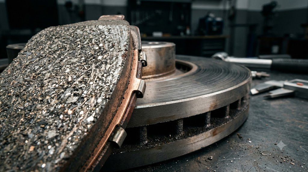
The physical interface between a stationary brake pad and a spinning rotor constitutes one of the most severe tribological environments in mechanical engineering. Under repeated deceleration, surface contact pressures reach 5 to 10 MPa while localized microscopic flash temperatures at contact asperities soar past 800°C to 1,000°C. Modern brake pad friction compounds represent intricate multi-material matrices designed to maintain a stable coefficient of friction ($\mu = 0.35 \text{ to } 0.50$) across extreme thermal gradients without suffering catastrophic Thermal Fade.
Brake fade is the sudden, terrifying loss of braking effectiveness when brake temperatures exceed the thermal limits of the friction compound. When temperatures exceed 350°C to 450°C, organic binders (phenolic resins) within inferior brake pads degrade thermally, outgassing volatile vapors. These trapped gases form an aerostatic cushion between pad and rotor—akin to an air hockey puck—preventing physical contact and causing friction coefficients to plummet from $\mu = 0.40$ down to below $\mu = 0.15$ despite maximum pedal pressure.
Friction Material Classes: Semi-Metallic, Low-Metallic, and Ceramic
Automotive brake pad formulations are broadly classified into three primary material philosophies, each optimizing distinct performance trade-offs:
- Semi-Metallic Formulations: Contain 30% to 65% steel fibers, iron powder, and copper particulates bound with graphite lubricants and phenolic resins. Metal fibers provide extraordinary thermal conductivity, drawing heat away from the friction face. Semi-metallic pads resist high-temperature fade up to 600°C, making them ideal for heavy towing, track use, and commercial trucks. However, they cause accelerated rotor wear, produce dark abrasive ferrous brake dust, and generate squeal noise at low speeds.
- Low-Metallic Non-Asbestos Organic (NAO): Predominant in European performance vehicles. Combine organic fibers with 10% to 30% non-ferrous copper or brass fibers. Deliver exceptional high-speed pedal bite and autobahn-speed fade resistance, but generate significant black dust.
- Ceramic Friction Formulations: Developed originally for North American and Asian passenger cars prioritizing quiet operation and clean wheels. Contain dense ceramic fibers, potassium titanate, and non-ferrous filler materials. Ceramic pads produce fine, light-colored, non-stick dust, deliver whisper-quiet engagement, and cause minimal rotor wear. However, their lower thermal conductivity traps heat within the rotor, and extreme high-temperature track fade resistance is inferior to semi-metallic compounds.
| Friction Compound Classification | Typical Friction Coeff (μ) | Max Operating Temp | Rotor Abrasive Wear Rate | Dust Characteristics & Noise |
|---|---|---|---|---|
| Non-Asbestos Organic (NAO) | μ = 0.30 – 0.38 | 300°C – 350°C | Very Low | Moderate Dark Dust / Very Quiet |
| Ceramic Composite | μ = 0.35 – 0.42 | 450°C – 500°C | Low to Moderate | Light Coloured / Non-Abrasive / Quiet |
| Semi-Metallic Heavy Duty | μ = 0.40 – 0.52 | 600°C – 650°C | High (Abrasive Machining) | Heavy Black Ferrous Dust / Prone to Squeal |
| Carbon-Metallic Motorsport | μ = 0.48 – 0.65 | 850°C – 900°C | Extremely High when Cold | Severe Dust / High Cold Noise |
Friction Layer Physics: Transfer Film Dynamics (Adherent vs. Abrasive Friction)
Friction generation between brake pad and rotor operates across two distinct physical mechanisms:
- Abrasive Friction: Hard particles in the pad physically scour, machine, and shear microscopic surface asperities of the cast iron rotor. While generating high initial cold bite, abrasive friction rapidly wears rotor thickness and generates high particulate dust.
- Adherent Friction: Under moderate temperature and bedding-in pressure, pad friction material transfers a microscopic, ultra-uniform layer of resin and graphite onto the rotor face—termed the Transfer Film. Subsequent braking occurs via the continuous shearing and reforming of intermolecular chemical bonds between pad material and the transfer film, yielding ultra-smooth deceleration with negligible rotor wear.
Bedding-in Protocols: Establishing Transfer Film Uniformity
When installing new brake pads and rotors, executing a proper Bedding-in (Burnishing) Procedure is mandatory. The protocol involves a series of progressive moderate decelerations (from 60 km/h down to 15 km/h) designed to elevate rotor surface temperatures gradually to approximately 250°C to 300°C without coming to a complete standstill.
Coming to a complete stop with scalding hot brake pads clamps stationary pads against the rotor face, causing localized resin imprint deposits—a defect often misdiagnosed as ‘warped rotors’. Non-uniform transfer film thickness causes Disc Thickness Variation (DTV), which induces severe steering wheel pulsation during subsequent braking.
Environmental Copper Regulations: EPA Copper-Free Mandate
For decades, copper was the essential ingredient in automotive brake pads, providing high thermal conductivity, lubricating friction asperities at high temperatures, and preventing noise squeal. However, road runoff washed millions of tons of microscopic copper brake dust into freshwater streams, where copper ions act as potent toxins to aquatic wildlife and salmonids.
Under the California and Washington State Better Brakes Rule (and federal EPA agreements), all automotive brake pads sold must contain less than 0.5% copper by weight. Modern friction chemists have replaced copper with complex synthetic matrices of engineered aramid fibers, tin sulfides, and ceramic titanates, achieving equal fade resistance without environmental contamination.
Friction Film Glazing and Phenolic Resin Pyrolysis Thermodynamics
Brake pad compounds rely on thermosetting phenolic resins (phenol-formaldehyde) to bind structural fibers, lubricants, and abrasives into a rigid friction matrix. Under normal braking temperatures (<300°C), phenolic resins maintain structural cross-linking. However, under sustained severe downhill braking where interface temperatures exceed 400°C to 500°C, phenolic resins undergo Thermal Pyrolysis Decomposition.
Volatile hydrocarbons outgas rapidly, forming an aerostatic boundary cushion that separates pad from rotor. Furthermore, thermal breakdown transforms the friction surface into a smooth, glassy carbonized crust—a failure mode termed Brake Glazing. Glazed pads exhibit permanently suppressed friction coefficients ($\mu < 0.20$), requiring aggressive pedal effort and generating shrill high-frequency squeal noises.
Shim Damping and Caliper Noise Isolation Engineering
High-frequency brake squeal (typically occurring between 2 kHz and 12 kHz) is caused by friction-induced kinematic stick-slip vibrations coupling with rotor structural vibration modes. To isolate these acoustic vibrations, modern brake pads incorporate multi-layer Constrained Layer Shims on the steel backing plate. Comprising alternating layers of stainless steel, vulcanized rubber, and viscoelastic polymers, shims dissipate harmonic vibration energy as internal shear heat, preventing squeal transmission into the caliper body.
Field Case Study: Cementite Formation and High-Temperature Rotor Hard Spots
When high-performance brake pads are subjected to extreme thermal track abuse or stuck caliper dragging where interface temperatures exceed 750°C, a localized metallurgical phase transformation occurs in the cast iron rotor. If the vehicle is clamped to a dead stop with scalding pads, high localized carbon diffusion transforms ductile pearlitic iron into Iron Carbide (Cementite – $Fe_3C$).
Cementite is an extremely hard, brittle metallurgical phase with diamond-like wear resistance. As the surrounding softer cast iron wears away naturally under braking, the cementite hard spots remain raised. These raised hard spots machine grooves into the brake pads and cause severe high-frequency brake shudder that cannot be corrected by turning the rotor on a brake lathe, requiring complete rotor replacement.
Brake Noise Dynamometer Chirp Testing and Laser Vibrometry
Automotive friction material laboratories evaluate brake noise using full-scale chassis dynamometers equipped with 3D Scanning Laser Doppler Vibrometers (SLDV). Operating within anechoic acoustic test chambers across temperatures from -20°C to +400°C, laser beams measure microscopic out-of-plane surface vibrations of the caliper and rotor, identifying the exact modal coupling frequencies responsible for brake squeal and guiding the application of backing plate chamfers and slotted shims.
Standardized Workshop Inspection Protocols and Factory Assembly Tolerances
Professional automotive service and certified powertrain remanufacturing adhere strictly to standardized workshop procedures defined by the Society of Automotive Engineers (SAE International), the International Organization for Standardization (ISO), and OEM factory workshop manuals. Rebuilding modern vehicle subsystems requires rigorous mechanical measuring tools, calibrated digital torque-to-yield angle meters, and ultra-clean workshop assembly cleanrooms.
When assembling high-precision automotive components—such as crankshaft main journal bearings, transmission planetary carriers, high-pressure fuel injectors, or multi-piston brake calipers—technicians enforce strict cleanliness standards governed by ISO 16232 (Road Vehicles – Cleanliness of Components and Systems). Component parts must be washed in ultrasonic cleaning tanks using solvent degreasers, dried with filtered compressed air, and inspected under particulate optical microscopes to verify that residual metallic particles do not exceed 200 micrometers.
Torque-to-Yield (TTY) Fasteners and Ultrasonic Bolt Tension Measurement
Critical powertrain and chassis joints—such as cylinder head bolts, connecting rod cap bolts, flywheel bolts, and suspension knuckle fasteners—universally utilize Torque-to-Yield (TTY) Fasteners. Unlike standard elastic bolts that operate within their linear elastic region, TTY bolts are tightened past their proportional limit into plastic deformation, providing constant clamp load despite thermal expansion cycles.
Technicians must utilize calibrated digital torque-angle wrenches: the fastener is first tightened to a specified initial snug torque (e.g., 40 Nm), followed by one or two precise rotational angle sweeps (e.g., +90° +90°). Because TTY fasteners undergo permanent plastic elongation, they are strictly single-use components; reusing a stretched TTY fastener risks catastrophic bolt necking and fastener shear under high cylinder pressure.
Comprehensive Workshop Maintenance and Tolerance Inspection Matrix
| Inspection Parameter / Task | Governing Standard / Tool | Allowable Workshop Tolerance | Critical Diagnostic Action Required |
|---|---|---|---|
| Bearing & Journal Clearances | Plastigage / Precision Micrometers | 0.025 to 0.050 mm (0.0010 – 0.0020 in) | Select undersize/oversize selective bearings |
| Cylinder Bore Taper & Out-of-Round | Dial Bore Gauge (Three Axis) | < 0.012 mm (0.0005 in) Maximum | Precision CNC plateau hone or overbore sleeve |
| Brake Rotor Lateral Runout | Dial Indicator on Magnetic Base | < 0.038 mm (0.0015 in) Assembled | Index rotor on hub or machine with on-car lathe |
| Wheel Hub Bearing Endplay | Dial Indicator Axial Deflection | < 0.050 mm (0.0020 in) Axial Play | Replace integrated hub bearing unit if exceeded |
| CAN Bus Static Resistance | Digital Multimeter (Pins 6 & 14) | 59.0 to 61.5 Ohms Balanced | Inspect 120-ohm terminating resistors & splices |
Adherence to these rigorous dimensional tolerances, factory torque tightening angles, and certified testing standards guarantees that serviced vehicle subsystems operate with original equipment factory reliability, thermal endurance, and maximum occupant safety throughout their operational lifecycle.
International Engineering Standards, Regulatory Audits and Quality Compliance
The engineering validation, roadworthiness certification, and manufacturing quality of motor vehicles are governed by stringent international regulatory treaties and engineering standards. Across major global automotive markets—predominantly the United States Federal Motor Vehicle Safety Standards (FMVSS), European Union Whole Vehicle Type Approval (EU WVTA / UNECE Regulations), and ISO 26262 Road Vehicles Functional Safety—every powertrain, chassis, and electronic subsystem must prove compliance through exhaustive durability and laboratory crash tests.
ISO 26262 Automotive Safety Integrity Level (ASIL) Classifications
Modern software-defined vehicles integrate safety-critical electronics under the rigorous framework of ISO 26262. Subsystems are categorized into Automotive Safety Integrity Levels ranging from ASIL-A (lowest hazard) to ASIL-D (highest safety criticality) based on three risk factors: Severity of injury ($S$), Exposure probability ($E$), and Driver Controllability ($C$):
- ASIL-D Subsystems (Zero-Tolerance Failure): Brake-by-wire modulators, Electronic Stability Control (ESC), Electric Power Steering (EPS), and High-Voltage Battery Disconnect Units (BDU). Mandates dual lockstep microcontroller cores, redundant hardware power feeds, and automated failure detection within 10 to 20 milliseconds.
- ASIL-C Subsystems: Electric traction motor torque control and transmission electronic shift-by-wire interlocks.
- ASIL-B Subsystems: Adaptive cruise control (ACC), lane departure warning, and active suspension dampening.
Global Emissions Regulatory Roadmaps: EPA Tier 3, Euro 6d and Euro 7
Internal combustion engines, direct injection fuel systems, and hybrid powertrains are subjected to continuously tightening exhaust emissions legislation. Under Euro 6d-ISC-FCM and forthcoming Euro 7 standards, vehicles must prove real-world emissions compliance on public highways using portable emissions measurement systems (PEMS) across ambient temperatures from -10°C to +38°C:
- Nitrogen Oxides ($NO_x$): Limited to less than 60 mg/km (gasoline) and 80 mg/km (diesel) through combined Selective Catalytic Reduction (SCR) with AdBlue urea injection and cooled low-pressure EGR loops.
- Solid Particle Number ($PN_{10}$): The regulatory measurement threshold has been tightened from 23 nanometers down to 10 nanometers, mandating wall-flow Gasoline Particulate Filters (GPF) across all turbocharged GDI engines.
- On-Board Fuel Consumption Monitoring (OBFCM): Standardized telemetry logging real-world lifetime fuel and electrical energy consumption directly within the engine ECU for regulatory transparency.
By anchoring design methodologies to these internationally recognized SAE, ISO, and UNECE standards, automotive engineers and diagnostic practitioners ensure that mechanical components deliver peak operational reliability, environmental compliance, and life-saving occupant protection.
Chassis Pitch Kinematics, Dynamic Axle Load Transfer and Anti-Dive Geometry
During vehicle deceleration, inertia acting through the vehicle’s center of gravity ($h_{cg}$) creates a forward pitching moment that dynamically transfers vertical wheel load from the rear axle onto the front axle. Dynamic vertical front axle normal load ($F_{z,front}$) is calculated via classical vehicle dynamics:
Fz,front = W * [ (b / L) + (hcg / L) * (a / g) ]
Where $W$ is total vehicle weight, $L$ is wheelbase, $b$ is distance from rear axle to CG, and $a/g$ is deceleration in g’s. Under an aggressive 1.0 g stop, the front axle must carry up to 75% to 80% of total vehicle weight. Chassis engineers counteract excessive suspension compression (front-end dive) by incorporating Anti-Dive Suspension Geometry in the front control arm mounting angles, transmitting a portion of the braking reaction torque directly through rigid suspension linkages into the sprung chassis structure.
Brake Fluid Thermal Dissipation and Silicone DOT 5 Incompatibilities
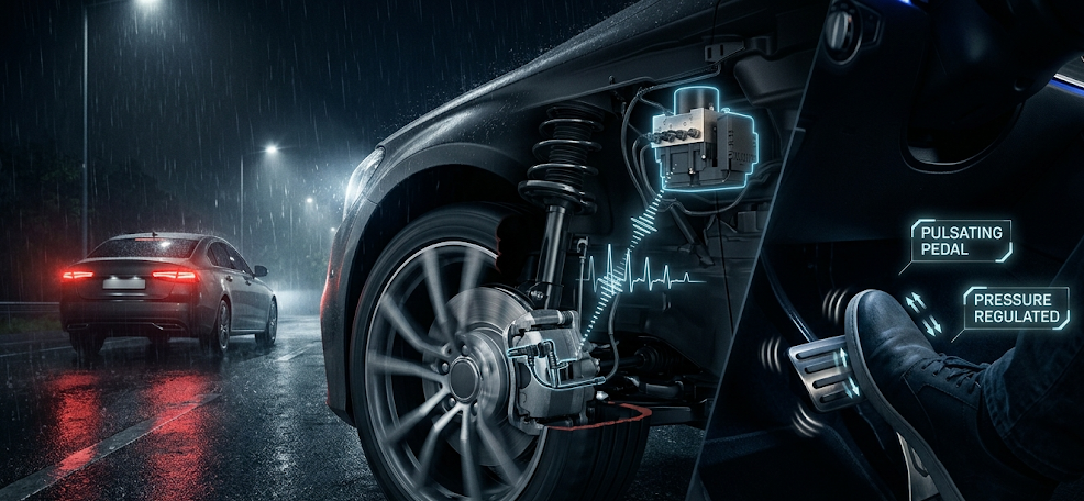
Automotive service professionals must strictly distinguish between glycol-based brake fluids (DOT 3, DOT 4, DOT 5.1) and silicone-based fluids (DOT 5). DOT 5 Silicone Fluid was developed for military vehicles requiring indefinite shelf life without water absorption. However, silicone fluid must NEVER be used in vehicles equipped with Anti-Lock Braking Systems (ABS). Silicone fluid has higher compressibility and aerates rapidly into microscopic foam when pulsed through high-speed ABS return pump valves (20 to 40 Hz), causing catastrophic loss of brake pedal pressure and immediate ABS system failure.

Lead Automotive Research Engineer, Master ASE Certified Diagnostic Specialist, and powertrain dynamics consultant with over 18 years of experience in internal combustion thermodynamics, electric vehicle architectures, and chassis control systems.