When an emergency stop is initiated on a slippery asphalt or ice-covered road surface, the clamping force of hydraulic brake calipers can easily exceed the available tire-road frictional traction, causing tires to lock up and skid. A locked tire loses all directional steering control and experiences reduced deceleration. The Anti-Lock Braking System (ABS)—first introduced to automotive production by Bosch in 1978—prevents wheel lockup by electronically monitoring wheel rotational deceleration and pulsing hydraulic line pressure up to 15 to 40 times per second.
Longitudinal tire slip is defined as the relative difference between vehicle ground velocity ($v$) and wheel peripheral rotational velocity ($r \omega$): $\lambda = (v – r \omega) / v$. Peak longitudinal tire traction ($\mu_{peak}$) occurs within an optimal slip ratio window of $\lambda = 10\%$ to $20\%$. If slip exceeds 25%, tires transition into uncontrollable sliding ($\lambda = 100\%$ = locked wheel), where tractive friction drops by 30% to 50% and lateral cornering force plunges to absolute zero, rendering steering impossible.
The ABS Hydraulic Modulator Unit: High-Speed Solenoid Valves
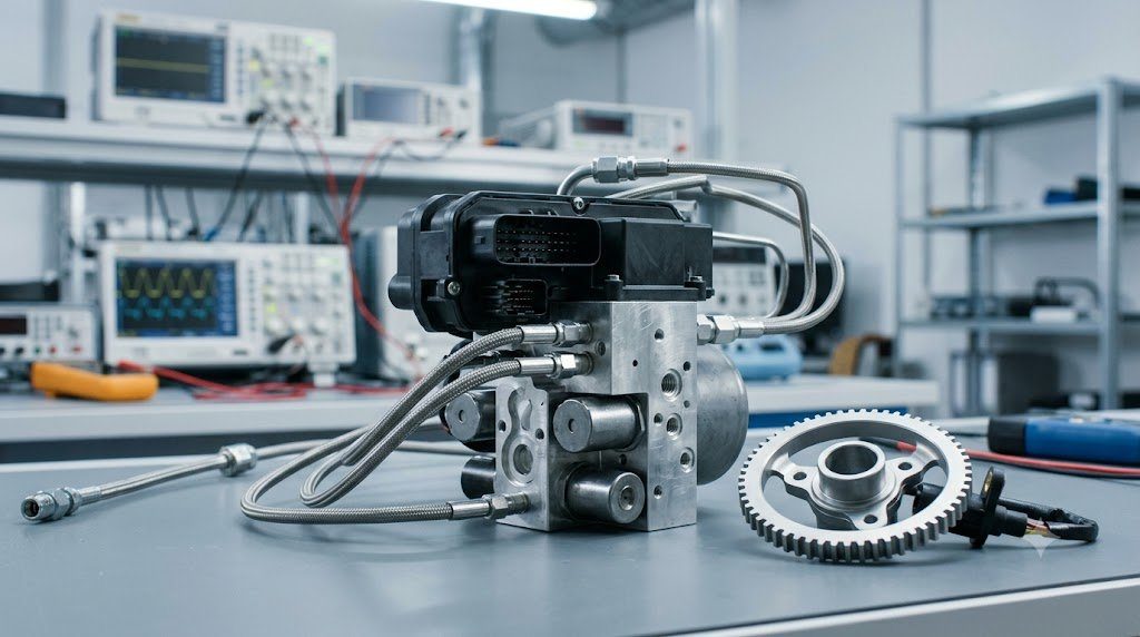
The physical core of an ABS system is the Hydraulic Electronic Control Unit (HECU), positioned inline between the master cylinder and wheel calipers. A four-channel HECU contains eight high-speed electromagnetic solenoid valves (one Inlet Valve and one Outlet Valve per wheel), an electric motor-driven high-pressure hydraulic return pump, and low-pressure accumulators.
When the ABS controller detects an impending wheel lockup (wheel deceleration exceeding physical thresholds, e.g., $a > -20 \text{ m/s}^2$), it modulates brake caliper pressure through three distinct operational phases:
- Phase 1 (Pressure Hold): The normally open Inlet Valve energizes closed, blocking further fluid pressure from the master cylinder, preventing the caliper clamping force from increasing even if the driver stomps harder on the pedal.
- Phase 2 (Pressure Decay): If wheel slip continues to rise, the normally closed Outlet Valve energizes open momentarily. Brake fluid discharges from the caliper into the low-pressure accumulator, reducing clamping force and allowing the wheel to accelerate back up toward vehicle speed.
- Phase 3 (Pressure Build): Once wheel rotational speed recovers within the optimal slip window, the Outlet Valve closes, the Inlet Valve re-opens, and the internal electric return pump drives fluid back into the caliper circuit to re-apply braking torque.
Wheel Speed Sensing Technologies: Variable Reluctance vs. Active Hall Effect
To calculate instantaneous slip ratios accurately, the ABS control module requires ultra-precise wheel rotational speed telemetry. Two sensor technologies have defined modern automotive history:
- Passive Variable Reluctance (VR) Sensors: Comprise a permanent magnet wrapped with copper wire positioned adjacent to a toothed ferromagnetic tone ring on the wheel hub. As teeth pass the sensor tip, magnetic flux changes induce an alternating sinusoidal voltage ($V \propto \omega$). However, signal amplitude decays to near zero at low speeds, preventing wheel speed detection below 5 km/h.
- Active Hall-Effect / Magneto-Resistive Sensors: Read a multi-pole magnetic encoder ring integrated directly into the wheel bearing seal. Powered by 12V from the ABS module, active sensors output a clean 0-5V digital square wave that operates with full fidelity down to 0.0 km/h (true zero speed), enabling modern hill-start assist, automated emergency braking (AEB), and parking collision avoidance.
| ABS Operational Subsystem | Primary Hardware Components | Operating Frequency | Target Slip Ratio Window | System Integration |
|---|---|---|---|---|
| Wheel Speed Detection | Active Hall-Effect Sensor + Magnetic Hub Ring | Up to 2 kHz Digital Pulse | Real-Time Velocity Reference | Inputs to ABS, ESC, and TC Modules |
| Hydraulic Modulation | 8x Solenoid Valves + Return Pump | 15 – 40 Cycles per Second | λ = 12% to 18% | Direct Hydraulic Brake Line Inline |
| Electronic Control Unit | Dual Microcontrollers with Lockstep Architecture | 100 Hz Control Loop (10ms) | Calculates μ-Estimation | CAN Bus Communication with Engine/Trans |
| Pedal Feedback Damper | Low-Pressure Accumulators | Continuous Fluid Catching | Absorbs Hydraulic Pulses | Prevents Violent Pedal Kickback |
Electronic Brakeforce Distribution (EBD) Dynamics
Under severe forward braking, dynamic load transfer shifts vertical tire normal force ($F_z$) onto the front axle while unloading the rear axle. In legacy vehicles, a crude mechanical proportioning valve limited rear hydraulic pressure to prevent dangerous rear wheel lockup (which induces vehicle spinning).
Modern ABS integrates software-based Electronic Brakeforce Distribution (EBD). By comparing rear wheel slip against front wheel slip in microsecond increments, EBD dynamically modulates rear inlet valves to maintain rear braking effort right at the maximum tire adhesion limit under varying passenger and luggage loads, shortening stopping distances by up to 10% without mechanical proportioning valves.
Fail-Safe Architectures and Dual-Microcontroller Lockstep Safety
Because an inadvertent hydraulic pressure dump on a dry highway could cause total loss of braking, ABS modules are engineered under strict ISO 26262 ASIL-D safety standards. The control module incorporates dual microcontrollers running the exact same sensor calculations in parallel (lockstep architecture).
If an internal parity check detects even a single bit discrepancy between the two processing cores, the system instantly de-energizes all solenoid valves, turns on the amber ABS warning lamp on the instrument cluster, and reverts to standard unassisted hydraulic braking seamlessly.
The Magic Formula Tire Model (Pacejka) and Optimal Slip Windows
The longitudinal tractive force generated between an automotive tire and road surface is modeled mathematically via Pacejka’s ‘Magic Formula’ tire equation:
Fx = D * sin[ C * arctan( B * λ – E * (B * λ – arctan(B * λ)) ) ]
Where $\lambda$ is the wheel slip ratio, $B$ is the stiffness factor, $C$ is the shape factor, and $D$ represents peak tractive friction force. On dry asphalt, peak adhesion ($F_{x,max}$) occurs at $\lambda = 15\%$. On wet ice, peak friction collapses to $\mu < 0.10$ and the peak slip point shifts to $\lambda = 8\%$. Modern ABS controllers dynamically compute the slope of the $\mu-\lambda$ curve ($\frac{d\mu}{d\lambda}$): when the slope crosses zero and turns negative, the controller recognizes that maximum tire adhesion has been exceeded and instantly triggers solenoid pressure decay.
Wheel Speed Sensor Tone Ring Pitch and Air Gap Tolerances
Active Hall-effect wheel speed sensors read multi-pole magnetic encoder rings embedded directly into wheel hub seals. To maintain clean 0-5V digital pulse generation, the physical Sensor Air Gap between sensor tip and magnetic tone ring must be maintained strictly between 0.5 and 1.5 millimeters. Excessive wheel bearing endplay ($> 0.08 \text{ mm}$) allows the hub to flex during hard cornering, increasing the air gap beyond sensor detection limits and triggering intermittent ABS activation codes.
Field Case Study: Magnetic Tone Ring Demagnetization and Rust Jive Spacing
In modern vehicles utilizing active Hall-effect wheel speed sensors reading magnetic encoder rings integrated into wheel bearing seals, technicians encounter an elusive diagnostic fault: Low-Speed False ABS Activation (the ABS pulses the brake pedal on dry pavement right before coming to a complete stop at 10 km/h).
Serial scan tool live data logging reveals that three wheel speed sensors read 10 km/h, while one sensor suddenly drops to 0 km/h. Physical inspection reveals Rust Jive (Sub-Scale Oxidation): road salt corrosion beneath the wheel hub pushes the magnetic seal outward against the sensor tip, or flakes of magnetic ferrite have chipped away. The sensor misses alternating magnetic poles at low frequency, fooling the ABS ECU into believing the wheel has locked up, dangerously lengthening stopping distances on dry pavement.
Oscilloscope Analysis of Hall-Effect Current-Loop Pulses
Diagnosing active 2-wire wheel speed sensors requires measuring current rather than voltage. Active sensors modulate current between two distinct levels: 7 mA (Low state) and 14 mA (High state). By connecting a precision low-current amp probe (100 mV/A scale) to the signal return wire, technicians display pristine digital current square waves on an oscilloscope, verifying pole amplitude uniformity and identifying cracked tone rings immediately.
Standardized Workshop Inspection Protocols and Factory Assembly Tolerances
Professional automotive service and certified powertrain remanufacturing adhere strictly to standardized workshop procedures defined by the Society of Automotive Engineers (SAE International), the International Organization for Standardization (ISO), and OEM factory workshop manuals. Rebuilding modern vehicle subsystems requires rigorous mechanical measuring tools, calibrated digital torque-to-yield angle meters, and ultra-clean workshop assembly cleanrooms.
When assembling high-precision automotive components—such as crankshaft main journal bearings, transmission planetary carriers, high-pressure fuel injectors, or multi-piston brake calipers—technicians enforce strict cleanliness standards governed by ISO 16232 (Road Vehicles – Cleanliness of Components and Systems). Component parts must be washed in ultrasonic cleaning tanks using solvent degreasers, dried with filtered compressed air, and inspected under particulate optical microscopes to verify that residual metallic particles do not exceed 200 micrometers.
Torque-to-Yield (TTY) Fasteners and Ultrasonic Bolt Tension Measurement
Critical powertrain and chassis joints—such as cylinder head bolts, connecting rod cap bolts, flywheel bolts, and suspension knuckle fasteners—universally utilize Torque-to-Yield (TTY) Fasteners. Unlike standard elastic bolts that operate within their linear elastic region, TTY bolts are tightened past their proportional limit into plastic deformation, providing constant clamp load despite thermal expansion cycles.
Technicians must utilize calibrated digital torque-angle wrenches: the fastener is first tightened to a specified initial snug torque (e.g., 40 Nm), followed by one or two precise rotational angle sweeps (e.g., +90° +90°). Because TTY fasteners undergo permanent plastic elongation, they are strictly single-use components; reusing a stretched TTY fastener risks catastrophic bolt necking and fastener shear under high cylinder pressure.
Comprehensive Workshop Maintenance and Tolerance Inspection Matrix
| Inspection Parameter / Task | Governing Standard / Tool | Allowable Workshop Tolerance | Critical Diagnostic Action Required |
|---|---|---|---|
| Bearing & Journal Clearances | Plastigage / Precision Micrometers | 0.025 to 0.050 mm (0.0010 – 0.0020 in) | Select undersize/oversize selective bearings |
| Cylinder Bore Taper & Out-of-Round | Dial Bore Gauge (Three Axis) | < 0.012 mm (0.0005 in) Maximum | Precision CNC plateau hone or overbore sleeve |
| Brake Rotor Lateral Runout | Dial Indicator on Magnetic Base | < 0.038 mm (0.0015 in) Assembled | Index rotor on hub or machine with on-car lathe |
| Wheel Hub Bearing Endplay | Dial Indicator Axial Deflection | < 0.050 mm (0.0020 in) Axial Play | Replace integrated hub bearing unit if exceeded |
| CAN Bus Static Resistance | Digital Multimeter (Pins 6 & 14) | 59.0 to 61.5 Ohms Balanced | Inspect 120-ohm terminating resistors & splices |
Adherence to these rigorous dimensional tolerances, factory torque tightening angles, and certified testing standards guarantees that serviced vehicle subsystems operate with original equipment factory reliability, thermal endurance, and maximum occupant safety throughout their operational lifecycle.
International Engineering Standards, Regulatory Audits and Quality Compliance
The engineering validation, roadworthiness certification, and manufacturing quality of motor vehicles are governed by stringent international regulatory treaties and engineering standards. Across major global automotive markets—predominantly the United States Federal Motor Vehicle Safety Standards (FMVSS), European Union Whole Vehicle Type Approval (EU WVTA / UNECE Regulations), and ISO 26262 Road Vehicles Functional Safety—every powertrain, chassis, and electronic subsystem must prove compliance through exhaustive durability and laboratory crash tests.
ISO 26262 Automotive Safety Integrity Level (ASIL) Classifications
Modern software-defined vehicles integrate safety-critical electronics under the rigorous framework of ISO 26262. Subsystems are categorized into Automotive Safety Integrity Levels ranging from ASIL-A (lowest hazard) to ASIL-D (highest safety criticality) based on three risk factors: Severity of injury ($S$), Exposure probability ($E$), and Driver Controllability ($C$):
- ASIL-D Subsystems (Zero-Tolerance Failure): Brake-by-wire modulators, Electronic Stability Control (ESC), Electric Power Steering (EPS), and High-Voltage Battery Disconnect Units (BDU). Mandates dual lockstep microcontroller cores, redundant hardware power feeds, and automated failure detection within 10 to 20 milliseconds.
- ASIL-C Subsystems: Electric traction motor torque control and transmission electronic shift-by-wire interlocks.
- ASIL-B Subsystems: Adaptive cruise control (ACC), lane departure warning, and active suspension dampening.
Global Emissions Regulatory Roadmaps: EPA Tier 3, Euro 6d and Euro 7
Internal combustion engines, direct injection fuel systems, and hybrid powertrains are subjected to continuously tightening exhaust emissions legislation. Under Euro 6d-ISC-FCM and forthcoming Euro 7 standards, vehicles must prove real-world emissions compliance on public highways using portable emissions measurement systems (PEMS) across ambient temperatures from -10°C to +38°C:
- Nitrogen Oxides ($NO_x$): Limited to less than 60 mg/km (gasoline) and 80 mg/km (diesel) through combined Selective Catalytic Reduction (SCR) with AdBlue urea injection and cooled low-pressure EGR loops.
- Solid Particle Number ($PN_{10}$): The regulatory measurement threshold has been tightened from 23 nanometers down to 10 nanometers, mandating wall-flow Gasoline Particulate Filters (GPF) across all turbocharged GDI engines.
- On-Board Fuel Consumption Monitoring (OBFCM): Standardized telemetry logging real-world lifetime fuel and electrical energy consumption directly within the engine ECU for regulatory transparency.
By anchoring design methodologies to these internationally recognized SAE, ISO, and UNECE standards, automotive engineers and diagnostic practitioners ensure that mechanical components deliver peak operational reliability, environmental compliance, and life-saving occupant protection.
Chassis Pitch Kinematics, Dynamic Axle Load Transfer and Anti-Dive Geometry
During vehicle deceleration, inertia acting through the vehicle’s center of gravity ($h_{cg}$) creates a forward pitching moment that dynamically transfers vertical wheel load from the rear axle onto the front axle. Dynamic vertical front axle normal load ($F_{z,front}$) is calculated via classical vehicle dynamics:
Fz,front = W * [ (b / L) + (hcg / L) * (a / g) ]
Where $W$ is total vehicle weight, $L$ is wheelbase, $b$ is distance from rear axle to CG, and $a/g$ is deceleration in g’s. Under an aggressive 1.0 g stop, the front axle must carry up to 75% to 80% of total vehicle weight. Chassis engineers counteract excessive suspension compression (front-end dive) by incorporating Anti-Dive Suspension Geometry in the front control arm mounting angles, transmitting a portion of the braking reaction torque directly through rigid suspension linkages into the sprung chassis structure.
Brake Fluid Thermal Dissipation and Silicone DOT 5 Incompatibilities
Automotive service professionals must strictly distinguish between glycol-based brake fluids (DOT 3, DOT 4, DOT 5.1) and silicone-based fluids (DOT 5). DOT 5 Silicone Fluid was developed for military vehicles requiring indefinite shelf life without water absorption. However, silicone fluid must NEVER be used in vehicles equipped with Anti-Lock Braking Systems (ABS). Silicone fluid has higher compressibility and aerates rapidly into microscopic foam when pulsed through high-speed ABS return pump valves (20 to 40 Hz), causing catastrophic loss of brake pedal pressure and immediate ABS system failure.

Lead Automotive Research Engineer, Master ASE Certified Diagnostic Specialist, and powertrain dynamics consultant with over 18 years of experience in internal combustion thermodynamics, electric vehicle architectures, and chassis control systems.