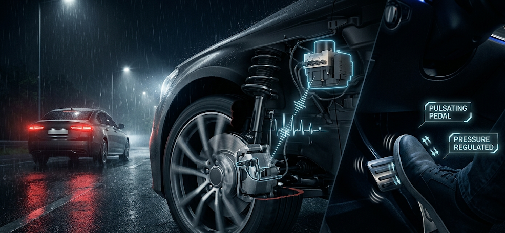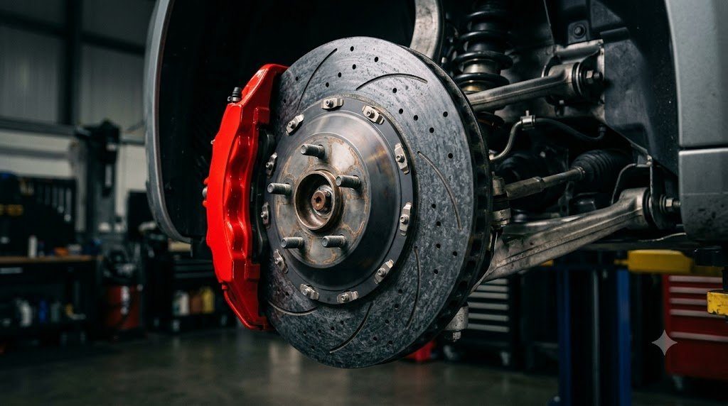
In automotive chassis engineering, the braking system is the primary safety-critical mechanism, responsible for dissipating kinetic energy into thermal enthalpy at deceleration rates that can exceed 1.0 to 1.3 g. At the core of every modern braking architecture is the Hydraulic Disc Brake, which utilizes fluid pressure multiplication governed by Pascal’s law to force high-friction pads against a spinning grey iron or carbon-ceramic brake rotor, converting hundreds of kilojoules of kinetic energy into heat in fractions of a second.
According to Pascal’s law, pressure applied to an enclosed, incompressible fluid is transmitted undiminished in all directions: $P = F_{in} / A_{master}$. When the driver exerts effort on the brake pedal, the mechanical pedal ratio ($MA \approx 4.0:1$) amplifies this force into the master cylinder. The generated hydraulic pressure ($P \approx 60 \text{ to } 120 \text{ bar}$) acts upon large-diameter caliper pistons ($A_{caliper}$), producing massive clamping forces ($F_{clamp} = P \cdot \sum A_{caliper}$) that can exceed 25,000 to 45,000 Newtons per wheel.
Rotor Metallurgy: Class 30 Grey Cast Iron and Thermal Fatigue
Automotive brake rotors are predominantly cast from Class 30 / Class 35 Grey Cast Iron (SAE J431 G3000), characterized by a pearlitic microstructure embedded with interconnected flakes of graphite. This metallurgical composition provides three indispensable physical properties:
- High Thermal Conductivity ($k \approx 45-50 \text{ W/m·K}$): Rapidly conducts thermal energy away from the friction interface into the ventilated rotor core, preventing surface scorching.
- Acoustic Vibration Damping: The internal graphite flake network absorbs high-frequency vibrations, suppressing brake squeal and harmonic resonance.
- Resistance to Thermal Warping: Withstands repeated temperature spikes up to 650°C without undergoing destructive phase transformation into brittle martensite.
In heavy braking events, surface temperatures cycle rapidly while the underlying rotor hub remains cooler. This differential expansion generates cyclical compressive thermal stresses that eventually manifest as Thermal Crazing (Heat Checking)—fine micro-cracks on the friction face that can propagate into catastrophic through-cracks if neglected.
Ventilated Rotor Vane Aerodynamics: Thermal Dissipation Modeling
Solid brake rotors are adequate for low-mass rear axles, but front axle rotors—which absorb up to 70% to 80% of total vehicle braking energy during forward weight transfer—must utilize Ventilated Discs with internal cooling vanes. Operating as internal centrifugal air pumps, rotating vanes draw cool ambient air in through the rotor center hat and expel it outward through the outer perimeter.
Modern performance rotors replace simple straight radial vanes with Curved Directional Vanes or Pillar Vane Arrays (Kangaroo Paw / Teardrop posts). Curved vanes accelerate airflow velocity by up to 35%, significantly boosting convective heat transfer coefficients ($h_c$) and reducing rotor peak operating temperatures by 70°C to 100°C under repeated high-speed stops.
| Rotor Architecture Type | Material Composition | Thermal Conductivity | Maximum Continuous Temp | Primary Production Application |
|---|---|---|---|---|
| Solid Grey Iron Disc | SAE G3000 Grey Cast Iron | 48 W/m·K | 450°C – 500°C | Compact Passenger Rear Axles |
| Straight Radial Vane | High-Carbon Pearlitic Iron | 50 W/m·K | 600°C | Mainstream Front Axle Rotors |
| Directional Curved Vane | Alloyed Cr-Mo Grey Iron | 52 W/m·K | 700°C | Sports Coupes & Track Day Packages |
| Carbon-Ceramic Matrix (CCM) | Siliconized Carbon Fiber (C/C-SiC) | 30 – 35 W/m·K | 1,000°C+ | Exotic Supercars & Hypercars |
Floating (Sliding) vs. Fixed Multi-Piston Caliper Mechanics
Hydraulic calipers clamp the friction pads against the spinning rotor faces using two distinct mechanical configurations:
- Floating / Sliding Caliper: The universal standard for production passenger cars. Features one or two hydraulic pistons located on the inboard side only. The caliper body slides along greased guide pins. When hydraulic pressure extends the inboard piston, reaction force pulls the entire caliper body inward, clamping the outboard pad against the rotor. While inexpensive and compact, guide pin binding, uneven pad taper wear, and caliper bracket flex under extreme pressure limit high-performance use.
- Fixed Multi-Piston Caliper: Bolted rigidly to the suspension knuckle without sliding pins. Features opposed pairs of pistons (4, 6, or 8 pistons total) on both inboard and outboard sides. Fixed calipers eliminate bracket deflection, provide instantaneous pedal response, and utilize differential piston sizing (smaller leading pistons, larger trailing pistons) to ensure uniform contact pressure and eliminate pad taper wear.
Brake Fluid Rheology: DOT 3, DOT 4, DOT 5.1 and Vapor Lock Hazards
Automotive brake fluid is a specialized synthetic hydraulic fluid formulated from polyglycol ethers and borate esters. Because brake fluid is in direct thermal contact with caliper pistons that reach hundreds of degrees Celsius, its boiling point is a critical safety threshold:
- Dry Boiling Point vs. Wet Boiling Point: Fresh, sealed brake fluid has a Dry Boiling Point exceeding 205°C (DOT 3) or 230°C (DOT 4). However, glycol-based fluids are highly hygroscopic, actively absorbing ambient atmospheric moisture through flexible rubber brake hoses at a rate of 1% to 2% water per year. Just 3.7% water content drops the boiling point down to the Wet Boiling Point (140°C for DOT 3, 155°C for DOT 4).
- Vapor Lock Catastrophic Failure: If degraded brake fluid exceeds its wet boiling point during hard mountain descent, moisture vaporizes into compressible gas bubbles within the caliper bore. When the driver depresses the brake pedal, the fluid compresses rather than transmitting hydraulic force—causing the pedal to sink completely to the floorboards with total loss of braking ability.
Rotor Thermal Energy Dissipation: Transient Heat Conduction Modeling
During a high-speed panic stop from 160 km/h (100 mph) to zero, an average passenger sedan dissipates approximately 1.2 MegaJoules of kinetic energy in less than 4.5 seconds. The instantaneous heat flux entering the front rotor friction rings is modeled via one-dimensional transient heat conduction:
qin = (ηfront * m * a * v) / (2 * Aswept) [W/m²]
At initial brake application, heat flux ($q_{in}$) exceeds 2.5 to 3.5 MW/m². Because convective air cooling is negligible during the initial two seconds, thermal energy is absorbed purely via the rotor’s volumetric specific heat capacity ($C_p \approx 460 \text{ J/kg·K}$). Peak surface flash temperatures soar to 600°C while the internal vane core remains at 150°C, establishing extreme through-thickness thermal gradients that drive plastic compressive deformation at the rotor surface.
Disc Thickness Variation (DTV) and Brake Torque Variation (BTV)
Brake pedal pulsation and steering wheel shudder are rarely caused by geometrically ‘warped’ rotors; rather, they are caused by Disc Thickness Variation (DTV). When rotor axial runout exceeds 0.05 millimeters (0.002 inches), the high spots of the wobbling rotor brush against the stationary brake pads once per wheel revolution as the vehicle cruises. Over thousands of highway miles, abrasive wear rubs microscopic thin spots on the rotor. Just 12 to 15 microns of thickness variation causes massive hydraulic pressure fluctuations (Brake Torque Variation – BTV) that shake the front suspension violently during braking.
Field Case Study: Caliper Slide Pin Corrosion and Unbalanced Pad Taper
In passenger vehicles operating in northern rust-belt regions exposed to road de-icing salts, the most prevalent mechanical braking defect is Caliper Slide Pin Seizure. The steel guide pins slide inside machined bores within the caliper mounting bracket, sealed by rubber accordion dust boots.
If a rubber boot tears or petroleum-based grease is mistakenly used (which swells and destroys EPDM rubber boots), moisture and road salt enter the bore. Corrosive rust expands within the slide pin clearance, seizing the floating caliper solid. When brakes are applied, only the inboard piston moves; the outboard pad cannot release, dragging permanently against the rotor face. The outboard pad wears down to bare steel within 5,000 kilometers, while the trapped friction heat boils caliper brake fluid and glazes the rotor face.
Brake Fluid Copper Strip Chemical Testing and Moisture Measurement
Professional brake service requires chemical analysis of brake fluid degradation. While simple boiling-point testers measure moisture percentage, the MAP (Motorist Assurance Program) standard mandates testing for Dissolved Copper Content using electrochemical test strips. As corrosion inhibitors in brake fluid deplete, acidic moisture attacks copper brazing inside steel brake lines. When dissolved copper levels exceed 200 parts per million (ppm), copper ions plate out on ABS modulator valves, sticking solenoid valves and mandating complete fluid flush.
Standardized Workshop Inspection Protocols and Factory Assembly Tolerances
Professional automotive service and certified powertrain remanufacturing adhere strictly to standardized workshop procedures defined by the Society of Automotive Engineers (SAE International), the International Organization for Standardization (ISO), and OEM factory workshop manuals. Rebuilding modern vehicle subsystems requires rigorous mechanical measuring tools, calibrated digital torque-to-yield angle meters, and ultra-clean workshop assembly cleanrooms.
When assembling high-precision automotive components—such as crankshaft main journal bearings, transmission planetary carriers, high-pressure fuel injectors, or multi-piston brake calipers—technicians enforce strict cleanliness standards governed by ISO 16232 (Road Vehicles – Cleanliness of Components and Systems). Component parts must be washed in ultrasonic cleaning tanks using solvent degreasers, dried with filtered compressed air, and inspected under particulate optical microscopes to verify that residual metallic particles do not exceed 200 micrometers.
Torque-to-Yield (TTY) Fasteners and Ultrasonic Bolt Tension Measurement
Critical powertrain and chassis joints—such as cylinder head bolts, connecting rod cap bolts, flywheel bolts, and suspension knuckle fasteners—universally utilize Torque-to-Yield (TTY) Fasteners. Unlike standard elastic bolts that operate within their linear elastic region, TTY bolts are tightened past their proportional limit into plastic deformation, providing constant clamp load despite thermal expansion cycles.
Technicians must utilize calibrated digital torque-angle wrenches: the fastener is first tightened to a specified initial snug torque (e.g., 40 Nm), followed by one or two precise rotational angle sweeps (e.g., +90° +90°). Because TTY fasteners undergo permanent plastic elongation, they are strictly single-use components; reusing a stretched TTY fastener risks catastrophic bolt necking and fastener shear under high cylinder pressure.
Comprehensive Workshop Maintenance and Tolerance Inspection Matrix
| Inspection Parameter / Task | Governing Standard / Tool | Allowable Workshop Tolerance | Critical Diagnostic Action Required |
|---|---|---|---|
| Bearing & Journal Clearances | Plastigage / Precision Micrometers | 0.025 to 0.050 mm (0.0010 – 0.0020 in) | Select undersize/oversize selective bearings |
| Cylinder Bore Taper & Out-of-Round | Dial Bore Gauge (Three Axis) | < 0.012 mm (0.0005 in) Maximum | Precision CNC plateau hone or overbore sleeve |
| Brake Rotor Lateral Runout | Dial Indicator on Magnetic Base | < 0.038 mm (0.0015 in) Assembled | Index rotor on hub or machine with on-car lathe |
| Wheel Hub Bearing Endplay | Dial Indicator Axial Deflection | < 0.050 mm (0.0020 in) Axial Play | Replace integrated hub bearing unit if exceeded |
| CAN Bus Static Resistance | Digital Multimeter (Pins 6 & 14) | 59.0 to 61.5 Ohms Balanced | Inspect 120-ohm terminating resistors & splices |
Adherence to these rigorous dimensional tolerances, factory torque tightening angles, and certified testing standards guarantees that serviced vehicle subsystems operate with original equipment factory reliability, thermal endurance, and maximum occupant safety throughout their operational lifecycle.
International Engineering Standards, Regulatory Audits and Quality Compliance
The engineering validation, roadworthiness certification, and manufacturing quality of motor vehicles are governed by stringent international regulatory treaties and engineering standards. Across major global automotive markets—predominantly the United States Federal Motor Vehicle Safety Standards (FMVSS), European Union Whole Vehicle Type Approval (EU WVTA / UNECE Regulations), and ISO 26262 Road Vehicles Functional Safety—every powertrain, chassis, and electronic subsystem must prove compliance through exhaustive durability and laboratory crash tests.
ISO 26262 Automotive Safety Integrity Level (ASIL) Classifications
Modern software-defined vehicles integrate safety-critical electronics under the rigorous framework of ISO 26262. Subsystems are categorized into Automotive Safety Integrity Levels ranging from ASIL-A (lowest hazard) to ASIL-D (highest safety criticality) based on three risk factors: Severity of injury ($S$), Exposure probability ($E$), and Driver Controllability ($C$):
- ASIL-D Subsystems (Zero-Tolerance Failure): Brake-by-wire modulators, Electronic Stability Control (ESC), Electric Power Steering (EPS), and High-Voltage Battery Disconnect Units (BDU). Mandates dual lockstep microcontroller cores, redundant hardware power feeds, and automated failure detection within 10 to 20 milliseconds.
- ASIL-C Subsystems: Electric traction motor torque control and transmission electronic shift-by-wire interlocks.
- ASIL-B Subsystems: Adaptive cruise control (ACC), lane departure warning, and active suspension dampening.
Global Emissions Regulatory Roadmaps: EPA Tier 3, Euro 6d and Euro 7
Internal combustion engines, direct injection fuel systems, and hybrid powertrains are subjected to continuously tightening exhaust emissions legislation. Under Euro 6d-ISC-FCM and forthcoming Euro 7 standards, vehicles must prove real-world emissions compliance on public highways using portable emissions measurement systems (PEMS) across ambient temperatures from -10°C to +38°C:
- Nitrogen Oxides ($NO_x$): Limited to less than 60 mg/km (gasoline) and 80 mg/km (diesel) through combined Selective Catalytic Reduction (SCR) with AdBlue urea injection and cooled low-pressure EGR loops.
- Solid Particle Number ($PN_{10}$): The regulatory measurement threshold has been tightened from 23 nanometers down to 10 nanometers, mandating wall-flow Gasoline Particulate Filters (GPF) across all turbocharged GDI engines.
- On-Board Fuel Consumption Monitoring (OBFCM): Standardized telemetry logging real-world lifetime fuel and electrical energy consumption directly within the engine ECU for regulatory transparency.
By anchoring design methodologies to these internationally recognized SAE, ISO, and UNECE standards, automotive engineers and diagnostic practitioners ensure that mechanical components deliver peak operational reliability, environmental compliance, and life-saving occupant protection.
Chassis Pitch Kinematics, Dynamic Axle Load Transfer and Anti-Dive Geometry
During vehicle deceleration, inertia acting through the vehicle’s center of gravity ($h_{cg}$) creates a forward pitching moment that dynamically transfers vertical wheel load from the rear axle onto the front axle. Dynamic vertical front axle normal load ($F_{z,front}$) is calculated via classical vehicle dynamics:
Fz,front = W * [ (b / L) + (hcg / L) * (a / g) ]
Where $W$ is total vehicle weight, $L$ is wheelbase, $b$ is distance from rear axle to CG, and $a/g$ is deceleration in g’s. Under an aggressive 1.0 g stop, the front axle must carry up to 75% to 80% of total vehicle weight. Chassis engineers counteract excessive suspension compression (front-end dive) by incorporating Anti-Dive Suspension Geometry in the front control arm mounting angles, transmitting a portion of the braking reaction torque directly through rigid suspension linkages into the sprung chassis structure.
Brake Fluid Thermal Dissipation and Silicone DOT 5 Incompatibilities
Automotive service professionals must strictly distinguish between glycol-based brake fluids (DOT 3, DOT 4, DOT 5.1) and silicone-based fluids (DOT 5). DOT 5 Silicone Fluid was developed for military vehicles requiring indefinite shelf life without water absorption. However, silicone fluid must NEVER be used in vehicles equipped with Anti-Lock Braking Systems (ABS). Silicone fluid has higher compressibility and aerates rapidly into microscopic foam when pulsed through high-speed ABS return pump valves (20 to 40 Hz), causing catastrophic loss of brake pedal pressure and immediate ABS system failure.

Lead Automotive Research Engineer, Master ASE Certified Diagnostic Specialist, and powertrain dynamics consultant with over 18 years of experience in internal combustion thermodynamics, electric vehicle architectures, and chassis control systems.