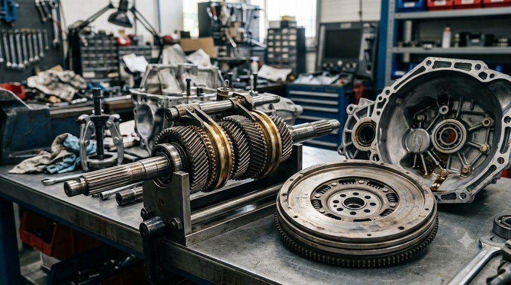
Despite the ascendancy of automated transmissions, the Manual Countershaft Transmission remains the gold standard for mechanical simplicity, lightweight packaging, and direct mechanical driver engagement. Operating with purely mechanical gear meshing without hydraulic pumping losses, manual transmissions achieve thermal transfer efficiencies exceeding 96% to 98%. Central to modern manual transmission operation are two mechanical assemblies: the Brass/Carbon Synchronizer Ring and the torsional vibration-absorbing Dual-Mass Flywheel (DMF).
In a constant-mesh manual transmission, all forward gear pairs are permanently meshed with each other, spinning freely on needle bearings around the output shaft. To engage a gear, the output shaft must be locked to that specific spinning gear. Because the output shaft and the target gear rotate at different angular velocities, attempting to force dog teeth together directly would result in violent gear grinding. The synchronizer acts as a miniature conical friction clutch that equalizes shaft speeds before dog teeth can physically engage.
Synchronizer Cone Tribology: The Mechanics of Speed Matching
The core component of a modern synchronizer assembly is the Blocker Ring (Synchronizer Ring), featuring an internal precision-ground conical surface with micro-grooves designed to cut through cold gear oil films. The synchronization sequence unfolds across four distinct mechanical phases:
- Phase 1 (Initial Contact): Moving the shift lever pushes the synchronizer operating sleeve and three internal shift keys toward the target gear, pressing the blocker ring cone against the mating external cone of the gear.
- Phase 2 (Blocking / Indexing): Frictional torque rotates the blocker ring by a few degrees until its chamfered external teeth align against the chamfered teeth of the sleeve. The angled tooth faces physically block the sleeve from advancing, preventing premature engagement.
- Phase 3 (Speed Equalization): The driver’s hand force applied to the shift lever is translated into intense axial pressure clamping the friction cones together. Cone friction rapidly accelerates or decelerates the input shaft and clutch disc until the target gear and output shaft rotate at identical RPM.
- Phase 4 (Engagement): Once relative speed reaches zero ($\Delta \omega = 0$), frictional torque vanishes, allowing the sleeve teeth to slide smoothly through the blocker ring teeth and engage the drive dogs on the gear.
Multi-Cone Synchronizers (Double and Triple-Cone Arrangements)
In low gears (1st and 2nd), the difference in rotational inertia between the input shaft assembly and output shaft is immense, requiring substantial synchronization energy. To reduce shift effort and prevent gear crunching, modern gearboxes employ Double-Cone and Triple-Cone Synchronizers.
A triple-cone synchronizer incorporates an outer ring, an intermediate cone, and an inner ring, multiplying the effective frictional contact area by three within the same axial footprint. Furthermore, modern high-performance synchronizers replace traditional brass friction faces with sintered bronze, molybdenum coatings, or woven carbon-fiber composites, withstanding extreme thermal energy during rapid speed shifting without cone glazing.
| Synchronizer Configuration | Friction Surface Material | Effective Friction Area Ratio | Typical Shift Effort | Primary Application |
|---|---|---|---|---|
| Single-Cone Synchronizer | Manganese Brass | 1.0x (Baseline) | Standard / High Effort in 1st/2nd | Higher Gears (4th, 5th, 6th) |
| Double-Cone Synchronizer | Sintered Bronze / Molybdenum | 2.0x Friction Area | 35% Lower Shift Effort | Mainstream 2nd and 3rd Gears |
| Triple-Cone Synchronizer | Woven Carbon-Fiber Matrix | 3.0x Friction Area | 50% Lower Shift Effort / Fast Spool | High-Performance 1st and 2nd Gears |
| Dog-Ring (Non-Synchro) | Hardened Alloy Steel Teeth | Zero (No Friction Cones) | Requires Rev-Matching / Violent Shift | Dedicated Motorsport Sequential |
Shift Tower Interlocks and Reverse Lockout Mechanisms
To prevent catastrophic mechanical binding, a manual transmission must incorporate fail-safe mechanical interlocks within its shift rail selector assembly. The primary safety interlocks include:
- Interlock Plungers (Cross-Shift Lockouts): Hardened steel balls or cylindrical pins positioned between adjacent shift rails. When one rail is moved into gear, the plunger is displaced into detents in neighboring rails, mechanically locking all other shift rails in neutral and preventing the transmission from engaging two gears simultaneously (which would lock the transmission solid and shatter gear teeth).
- Reverse Gear Inhibitor: A mechanical spring-loaded gate or electronic solenoid that prevents the driver from inadvertently moving the shift lever from 5th or 6th gear directly into Reverse while traveling forward at high speed.
The Dual-Mass Flywheel (DMF): Torsional Resonance Attenuation
Modern downsized internal combustion engines produce intense cyclic firing pulses that induce severe torsional vibrations in the crankshaft. In a traditional single-mass flywheel setup, these torsional vibrations travel directly into the manual transmission, causing loose gear teeth on unloaded gears to rattle against one another—a phenomenon known as Gearbox Neutral Rattle.
The Dual-Mass Flywheel (DMF) splits the flywheel into two masses: a Primary Mass bolted to the crankshaft and a Secondary Mass bolted to the clutch assembly, connected through curved circumferential arc springs submerged in silicone grease. The arc springs shift the drivetrain’s natural resonant torsional frequency below the engine’s idling speed (~400 RPM vs. 750 RPM idle), completely isolating the transmission from engine vibrations and ensuring quiet, vibration-free operation.
Clutch Cushion Deflation: Marcing Spring Rate and Engagement Modality
In a manual transmission friction clutch disc, the friction facings are not riveted directly to a flat steel plate; instead, they are riveted to a segmented, wavy spring-steel sheet known as the Marcing Spring (Cushion Spring). As the pressure plate clamps down, the wavy marcing springs compress elastically over 1.0 to 1.5 millimeters of travel.
This controlled axial deflection curves the clutch clamp load progressively over pedal travel, preventing violent on/off clutch grabbing. If marcing springs lose temper from severe clutch overheating, the clutch engages abruptly, causing violent vehicle shuddering and stalling during low-speed standing starts.
Shaft Bending Deflection and Tooth Misalignment Tolerances
Under maximum engine torque in 1st and 2nd gears, the separating and tangential gear forces ($F_r$ and $F_t$) push the transmission input and countershafts apart. Under DIN 3990 standards, maximum allowable shaft bending slope across gear tooth faces is strictly limited to less than 0.001 radians (0.05 degrees). Excessive casing flex or bearing wear allows shafts to splay outward, shifting tooth contact entirely onto gear tooth corners and causing premature tooth corner fracture.
Field Case Study: Aggressive Speed-Shifting and Blocker Ring Tooth Shearing
In high-performance manual transmissions subjected to aggressive track use or speed-shifting without full clutch pedal depression, the synchronizer assembly is subjected to severe shock loads. Moving the shift lever with brute muscular force while the clutch is partially dragging forces the synchronizer sleeve forward before cone friction has synchronized shaft speeds.
The hardened steel sleeve teeth slam violently against the chamfered brass or sintered bronze blocker ring teeth. Under repeated impacts, the pointed chamfers round off and fracture—a condition termed Synchronizer Tooth Shearing. Once the chamfers are destroyed, the blocker ring can no longer block the sleeve, resulting in violent gear grinding on every shift into 2nd or 3rd gear, requiring complete gearbox teardown.
Dial Indicator Backlash and Preload Setup in Tapered Roller Shaft Bearings
Rebuilding a manual transmission requires precise mechanical shimming of tapered roller shaft bearings. Technicians mount a precision dial indicator to the transmission input shaft, measuring axial endplay down to 0.01 mm. By calculating required selective shim thicknesses beneath bearing bearing races, technicians establish an exact factory preload of 0.05 to 0.10 mm negative endplay, ensuring the shafts do not deflect under maximum torque while preventing bearing thermal overheating.
Standardized Workshop Inspection Protocols and Factory Assembly Tolerances
Professional automotive service and certified powertrain remanufacturing adhere strictly to standardized workshop procedures defined by the Society of Automotive Engineers (SAE International), the International Organization for Standardization (ISO), and OEM factory workshop manuals. Rebuilding modern vehicle subsystems requires rigorous mechanical measuring tools, calibrated digital torque-to-yield angle meters, and ultra-clean workshop assembly cleanrooms.
When assembling high-precision automotive components—such as crankshaft main journal bearings, transmission planetary carriers, high-pressure fuel injectors, or multi-piston brake calipers—technicians enforce strict cleanliness standards governed by ISO 16232 (Road Vehicles – Cleanliness of Components and Systems). Component parts must be washed in ultrasonic cleaning tanks using solvent degreasers, dried with filtered compressed air, and inspected under particulate optical microscopes to verify that residual metallic particles do not exceed 200 micrometers.
Torque-to-Yield (TTY) Fasteners and Ultrasonic Bolt Tension Measurement
Critical powertrain and chassis joints—such as cylinder head bolts, connecting rod cap bolts, flywheel bolts, and suspension knuckle fasteners—universally utilize Torque-to-Yield (TTY) Fasteners. Unlike standard elastic bolts that operate within their linear elastic region, TTY bolts are tightened past their proportional limit into plastic deformation, providing constant clamp load despite thermal expansion cycles.
Technicians must utilize calibrated digital torque-angle wrenches: the fastener is first tightened to a specified initial snug torque (e.g., 40 Nm), followed by one or two precise rotational angle sweeps (e.g., +90° +90°). Because TTY fasteners undergo permanent plastic elongation, they are strictly single-use components; reusing a stretched TTY fastener risks catastrophic bolt necking and fastener shear under high cylinder pressure.
Comprehensive Workshop Maintenance and Tolerance Inspection Matrix
| Inspection Parameter / Task | Governing Standard / Tool | Allowable Workshop Tolerance | Critical Diagnostic Action Required |
|---|---|---|---|
| Bearing & Journal Clearances | Plastigage / Precision Micrometers | 0.025 to 0.050 mm (0.0010 – 0.0020 in) | Select undersize/oversize selective bearings |
| Cylinder Bore Taper & Out-of-Round | Dial Bore Gauge (Three Axis) | < 0.012 mm (0.0005 in) Maximum | Precision CNC plateau hone or overbore sleeve |
| Brake Rotor Lateral Runout | Dial Indicator on Magnetic Base | < 0.038 mm (0.0015 in) Assembled | Index rotor on hub or machine with on-car lathe |
| Wheel Hub Bearing Endplay | Dial Indicator Axial Deflection | < 0.050 mm (0.0020 in) Axial Play | Replace integrated hub bearing unit if exceeded |
| CAN Bus Static Resistance | Digital Multimeter (Pins 6 & 14) | 59.0 to 61.5 Ohms Balanced | Inspect 120-ohm terminating resistors & splices |
Adherence to these rigorous dimensional tolerances, factory torque tightening angles, and certified testing standards guarantees that serviced vehicle subsystems operate with original equipment factory reliability, thermal endurance, and maximum occupant safety throughout their operational lifecycle.
International Engineering Standards, Regulatory Audits and Quality Compliance
The engineering validation, roadworthiness certification, and manufacturing quality of motor vehicles are governed by stringent international regulatory treaties and engineering standards. Across major global automotive markets—predominantly the United States Federal Motor Vehicle Safety Standards (FMVSS), European Union Whole Vehicle Type Approval (EU WVTA / UNECE Regulations), and ISO 26262 Road Vehicles Functional Safety—every powertrain, chassis, and electronic subsystem must prove compliance through exhaustive durability and laboratory crash tests.
ISO 26262 Automotive Safety Integrity Level (ASIL) Classifications
Modern software-defined vehicles integrate safety-critical electronics under the rigorous framework of ISO 26262. Subsystems are categorized into Automotive Safety Integrity Levels ranging from ASIL-A (lowest hazard) to ASIL-D (highest safety criticality) based on three risk factors: Severity of injury ($S$), Exposure probability ($E$), and Driver Controllability ($C$):
- ASIL-D Subsystems (Zero-Tolerance Failure): Brake-by-wire modulators, Electronic Stability Control (ESC), Electric Power Steering (EPS), and High-Voltage Battery Disconnect Units (BDU). Mandates dual lockstep microcontroller cores, redundant hardware power feeds, and automated failure detection within 10 to 20 milliseconds.
- ASIL-C Subsystems: Electric traction motor torque control and transmission electronic shift-by-wire interlocks.
- ASIL-B Subsystems: Adaptive cruise control (ACC), lane departure warning, and active suspension dampening.
Global Emissions Regulatory Roadmaps: EPA Tier 3, Euro 6d and Euro 7
Internal combustion engines, direct injection fuel systems, and hybrid powertrains are subjected to continuously tightening exhaust emissions legislation. Under Euro 6d-ISC-FCM and forthcoming Euro 7 standards, vehicles must prove real-world emissions compliance on public highways using portable emissions measurement systems (PEMS) across ambient temperatures from -10°C to +38°C:
- Nitrogen Oxides ($NO_x$): Limited to less than 60 mg/km (gasoline) and 80 mg/km (diesel) through combined Selective Catalytic Reduction (SCR) with AdBlue urea injection and cooled low-pressure EGR loops.
- Solid Particle Number ($PN_{10}$): The regulatory measurement threshold has been tightened from 23 nanometers down to 10 nanometers, mandating wall-flow Gasoline Particulate Filters (GPF) across all turbocharged GDI engines.
- On-Board Fuel Consumption Monitoring (OBFCM): Standardized telemetry logging real-world lifetime fuel and electrical energy consumption directly within the engine ECU for regulatory transparency.
By anchoring design methodologies to these internationally recognized SAE, ISO, and UNECE standards, automotive engineers and diagnostic practitioners ensure that mechanical components deliver peak operational reliability, environmental compliance, and life-saving occupant protection.
Driveline Torsional Dynamics, Gear Lash Noise and Propeller Shaft Harmonics
In automotive drivetrain engineering, mechanical power transmission from the transmission output shaft to the driving wheel hubs involves an elastic driveline system susceptible to torsional resonance, gear lash rattle, and driveline shudder. Because the reciprocating internal combustion engine fires in discrete torque pulses, dynamic driveline torque fluctuates continuously about a mean value ($T(t) = T_0 + \sum T_k \sin(k \omega t)$).
If engine firing excitation harmonics coincide with the torsional natural frequency of the transmission main shaft, propeller shaft, or half-shaft axles (typically between 15 Hz and 45 Hz), violent torsional oscillations amplify through the drivetrain—a phenomenon known as Driveline Clunk and Tip-In Shudder. Drivetrain engineers optimize propeller shaft torsional stiffness by utilizing carbon-fiber composite driveshafts and tuned elastomeric guibo coupling discs that absorb torque shocks during sudden throttle transitions.
Hypoid Final Drive Kinematics and Extreme Pressure Tribology
Rear-wheel-drive and all-wheel-drive vehicles utilize a Hypoid Bevel Gear Differential in the rear axle, where the driving pinion shaft is offset below the ring gear center. Hypoid geometry allows a lower vehicle floorboard and larger pinion diameter, but introduces severe longitudinal sliding along the gear tooth flanks under extreme Hertzian contact pressures. Final drive differentials demand specialized GL-5 Hypoid Gear Lubricants formulated with high concentrations of thermally stable sulfur-phosphorus extreme-pressure (EP) additives. Under high flash temperatures, the EP additives react chemically with steel tooth surfaces to form sacrificial iron sulfide boundary films, preventing tooth welding and hypoid scuffing under extreme acceleration loads.

Lead Automotive Research Engineer, Master ASE Certified Diagnostic Specialist, and powertrain dynamics consultant with over 18 years of experience in internal combustion thermodynamics, electric vehicle architectures, and chassis control systems.