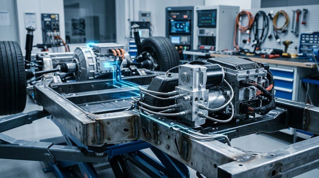
In the transition toward hybrid and battery electric vehicle (EV) architectures, the conventional paradigm of wasting vehicle kinetic energy entirely as friction heat is obsolete. Modern electrified powertrains utilize Regenerative Braking, transforming the high-voltage electric traction motor into a generator to decelerate the vehicle while capturing up to 70% to 90% of recoverable kinetic energy directly back into the lithium-ion traction battery pack.
The kinetic energy of a moving vehicle is formulated as $E_k = \frac{1}{2} m v^2$. In a conventional friction brake stop, this entire energy packet is converted irreversibly into waste thermal enthalpy. In an electric vehicle, regenerative deceleration applies negative electromagnetic torque ($T_{regen}$) through the traction motor. The recovered electrical power ($P_{regen} = T_{regen} \cdot \omega \cdot \eta_{gen}$) flows back through the inverter to charge the battery, extending real-world driving range by 15% to 25%.
Electro-Hydraulic Torque Blending: The Seamless Hand-Off Challenge
While electric motors provide powerful deceleration at moderate-to-high speeds, regenerative braking is fundamentally constrained by physical vehicle boundaries:
- Low-Speed Inability: As vehicle road speed approaches zero, motor angular velocity ($\omega$) drops toward zero, causing electromagnetic generator power ($P = T \omega$) to vanish. Friction brakes must execute the final vehicle stop.
- Battery State-of-Charge (SoC) Limits: If the traction battery is 100% fully charged, it cannot accept additional charging current without suffering lithium plating or thermal runaway. Regenerative braking must be disabled or curtailed.
- Emergency Braking Dynamics: Electric motors only decelerate driven wheels (front or rear in 2WD vehicles). Under aggressive emergency stops, high deceleration requires balanced 4-wheel friction braking to maintain chassis directional stability.
To ensure consistent, natural pedal feel, the vehicle must execute Braking Torque Blending: the Electronic Brake Control Module seamlessly blends regenerative motor torque and hydraulic friction caliper torque, ensuring total deceleration matches driver pedal demand precisely regardless of battery SoC or speed.
Brake-by-Wire Architectures: Decoupling the Driver’s Foot
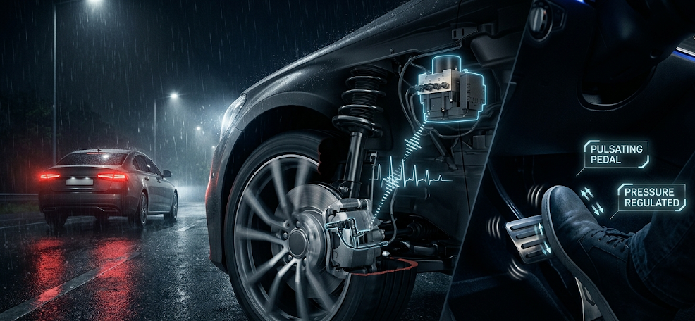
Achieving seamless torque blending is impossible with conventional vacuum brake boosters, because hydraulic fluid would physically pulse against the driver’s foot whenever motor regen kicked in. Modern EVs and hybrids deploy Integrated Brake-by-Wire (IBW) systems (e.g., Bosch iBooster, Continental MK C1, ZF IBC).
In an integrated brake-by-wire system, the physical brake pedal is completely decoupled from the hydraulic master cylinder during normal driving:
- Pedal Feel Simulator: The driver pushes against a spring-and-elastomer simulator that reproduces realistic hydraulic pedal resistance and travel. High-resolution redundant sensors measure pedal displacement and driver force.
- Electro-Mechanical Pressure Generation: A high-torque brushless DC electric motor drives a high-precision ball screw actuator to generate hydraulic pressure in the wheel calipers electronically, independently of driver foot movement.
| Brake Actuation Architecture | Pedal Coupling Type | Pressure Build Response Time | Regenerative Blending Efficiency | Primary Application |
|---|---|---|---|---|
| Conventional Vacuum Booster | Direct Mechanical Pushrod | 300 – 400 milliseconds | 0% (No Regeneration Support) | Legacy Internal Combustion Cars |
| Two-Box Electronic Booster (iBooster) | Decoupled via Servo Follower | 120 – 150 milliseconds | Up to 80% Energy Capture | Early EVs and Plug-in Hybrids |
| Integrated One-Box Brake-by-Wire | Fully Decoupled Electronic Simulator | 100 – 120 milliseconds | Up to 95% Energy Capture | Modern BEVs (Tesla, Porsche Taycan, Audi e-tron) |
| Dry Brake-by-Wire (EMB / Caliper) | Complete Elimination of Brake Fluid | Sub-50 milliseconds | 100% Programmable Blending | Next-Gen Software-Defined Vehicles |
One-Pedal Driving Dynamics and Friction Brake Corrosion
In many modern electric vehicles, calibrators enable One-Pedal Driving. When the driver lifts off the accelerator pedal, the vehicle automatically initiates aggressive regenerative braking (up to 0.2 to 0.3 g deceleration), bringing the vehicle to a full stop without touching the brake pedal.
While highly convenient for drivers, one-pedal driving introduces a severe unintended mechanical failure mode: Friction Brake Underutilization Corrosion. Because mechanical calipers are rarely engaged during suburban commutes, cast iron rotors are not cleaned by pad friction, allowing road moisture and winter salt to corrode rotor faces rapidly. To prevent this, modern EV controllers implement automated ‘brake cleaning cycles’, periodically applying light hydraulic caliper friction to sweep rust off rotor faces without notifying the driver.
Safety Redundancy: Level 3 Autonomous Hydraulic Fallback
Under international safety regulations (ECE R13-H), a fully electronic brake-by-wire vehicle must maintain mechanical fallback in the event of total electrical power failure. Integrated systems incorporate a normally open emergency hydraulic bypass valve.
If 12V vehicle electrical power fails completely, the bypass valve drops open instantaneously, mechanically reconnecting the driver’s brake pedal pushrod directly to the hydraulic master cylinder pistons, allowing the driver to stop the vehicle manually using muscular foot effort.
Cooperative Regenerative Deceleration Torque Allocation Algorithms
In modern electrified brake-by-wire systems, braking demand ($F_{demand}$) is parsed through a real-time dynamic Torque Allocation Matrix executed by the Vehicle Control Unit (VCU) every 10 milliseconds:
Ttotal = Tregen,front + Tregen,rear + Tfriction,front + Tfriction,rear
The controller prioritizes regenerative motor torque up to physical inverter and battery charge acceptance limits ($P_{charge,max} / \omega$). When driver demand exceeds maximum regenerative capacity (or when ABS slip intervention is detected), high-speed electro-hydraulic valves seamlessly inject hydraulic caliper pressure into the front and rear circuits to fulfill total vehicle deceleration without any perceived pedal transition by the driver.
Pedal Travel Simulator Spring-Elastomer Dynamic Hysteresis
Because the driver’s foot is physically isolated from hydraulic caliper lines in brake-by-wire systems, realistic pedal resistance is generated by an electronic Pedal Simulator. Incorporating a dual-rate mechanical spring paired with a polyurethane elastomer bumper, the simulator reproduces non-linear pedal feel: low initial resistance during free-play travel, followed by exponential progressive stiffening as simulated deceleration climbs past 0.5 g.
Field Case Study: Brake-by-Wire Pedal Simulator Drift and Plausibility DTCs
Integrated one-box brake-by-wire units (such as Bosch iBooster and Continental MK C1) utilize redundant sensor arrays to track driver braking intent. Two independent pedal travel sensors (Hall effect) and an integrated hydraulic master cylinder pressure transducer monitor pedal displacement ($S$) and hydraulic pressure ($P$).
Over hundreds of thousands of brake cycles, mechanical wear or moisture ingress into the pedal pivot can introduce angular sensor drift. The Electronic Brake Control Module runs continuous plausibility cross-checks: if measured pedal displacement does not correlate with simulated hydraulic chamber pressure within calibrated tolerance envelopes, the module flags critical safety DTCs (e.g., C1200 Pedal Sensor Plausibility Fault), illuminating the red brake warning lamp and transitioning the vehicle into manual hydraulic push-through fallback mode.
Automated Pressure Bleeding of Electro-Hydraulic Modulator Chambers
Bleeding air from an integrated brake-by-wire unit cannot be performed with traditional two-person pedal pumping; doing so will permanently trap microscopic air bubbles within internal electro-hydraulic accumulator valves. Technicians must connect a pressurized fluid bleeder (regulated to 2.0 bar) to the master cylinder reservoir and command an automated Diagnostic Scan Tool Bleed Routine. The scan tool cycles internal brushless DC motor solenoids and high-speed valves sequentially, sweeping trapped air out into caliper bleed screws.
Standardized Workshop Inspection Protocols and Factory Assembly Tolerances
Professional automotive service and certified powertrain remanufacturing adhere strictly to standardized workshop procedures defined by the Society of Automotive Engineers (SAE International), the International Organization for Standardization (ISO), and OEM factory workshop manuals. Rebuilding modern vehicle subsystems requires rigorous mechanical measuring tools, calibrated digital torque-to-yield angle meters, and ultra-clean workshop assembly cleanrooms.
When assembling high-precision automotive components—such as crankshaft main journal bearings, transmission planetary carriers, high-pressure fuel injectors, or multi-piston brake calipers—technicians enforce strict cleanliness standards governed by ISO 16232 (Road Vehicles – Cleanliness of Components and Systems). Component parts must be washed in ultrasonic cleaning tanks using solvent degreasers, dried with filtered compressed air, and inspected under particulate optical microscopes to verify that residual metallic particles do not exceed 200 micrometers.
Torque-to-Yield (TTY) Fasteners and Ultrasonic Bolt Tension Measurement
Critical powertrain and chassis joints—such as cylinder head bolts, connecting rod cap bolts, flywheel bolts, and suspension knuckle fasteners—universally utilize Torque-to-Yield (TTY) Fasteners. Unlike standard elastic bolts that operate within their linear elastic region, TTY bolts are tightened past their proportional limit into plastic deformation, providing constant clamp load despite thermal expansion cycles.
Technicians must utilize calibrated digital torque-angle wrenches: the fastener is first tightened to a specified initial snug torque (e.g., 40 Nm), followed by one or two precise rotational angle sweeps (e.g., +90° +90°). Because TTY fasteners undergo permanent plastic elongation, they are strictly single-use components; reusing a stretched TTY fastener risks catastrophic bolt necking and fastener shear under high cylinder pressure.
Comprehensive Workshop Maintenance and Tolerance Inspection Matrix
| Inspection Parameter / Task | Governing Standard / Tool | Allowable Workshop Tolerance | Critical Diagnostic Action Required |
|---|---|---|---|
| Bearing & Journal Clearances | Plastigage / Precision Micrometers | 0.025 to 0.050 mm (0.0010 – 0.0020 in) | Select undersize/oversize selective bearings |
| Cylinder Bore Taper & Out-of-Round | Dial Bore Gauge (Three Axis) | < 0.012 mm (0.0005 in) Maximum | Precision CNC plateau hone or overbore sleeve |
| Brake Rotor Lateral Runout | Dial Indicator on Magnetic Base | < 0.038 mm (0.0015 in) Assembled | Index rotor on hub or machine with on-car lathe |
| Wheel Hub Bearing Endplay | Dial Indicator Axial Deflection | < 0.050 mm (0.0020 in) Axial Play | Replace integrated hub bearing unit if exceeded |
| CAN Bus Static Resistance | Digital Multimeter (Pins 6 & 14) | 59.0 to 61.5 Ohms Balanced | Inspect 120-ohm terminating resistors & splices |
Adherence to these rigorous dimensional tolerances, factory torque tightening angles, and certified testing standards guarantees that serviced vehicle subsystems operate with original equipment factory reliability, thermal endurance, and maximum occupant safety throughout their operational lifecycle.
International Engineering Standards, Regulatory Audits and Quality Compliance
The engineering validation, roadworthiness certification, and manufacturing quality of motor vehicles are governed by stringent international regulatory treaties and engineering standards. Across major global automotive markets—predominantly the United States Federal Motor Vehicle Safety Standards (FMVSS), European Union Whole Vehicle Type Approval (EU WVTA / UNECE Regulations), and ISO 26262 Road Vehicles Functional Safety—every powertrain, chassis, and electronic subsystem must prove compliance through exhaustive durability and laboratory crash tests.
ISO 26262 Automotive Safety Integrity Level (ASIL) Classifications
Modern software-defined vehicles integrate safety-critical electronics under the rigorous framework of ISO 26262. Subsystems are categorized into Automotive Safety Integrity Levels ranging from ASIL-A (lowest hazard) to ASIL-D (highest safety criticality) based on three risk factors: Severity of injury ($S$), Exposure probability ($E$), and Driver Controllability ($C$):
- ASIL-D Subsystems (Zero-Tolerance Failure): Brake-by-wire modulators, Electronic Stability Control (ESC), Electric Power Steering (EPS), and High-Voltage Battery Disconnect Units (BDU). Mandates dual lockstep microcontroller cores, redundant hardware power feeds, and automated failure detection within 10 to 20 milliseconds.
- ASIL-C Subsystems: Electric traction motor torque control and transmission electronic shift-by-wire interlocks.
- ASIL-B Subsystems: Adaptive cruise control (ACC), lane departure warning, and active suspension dampening.
Global Emissions Regulatory Roadmaps: EPA Tier 3, Euro 6d and Euro 7
Internal combustion engines, direct injection fuel systems, and hybrid powertrains are subjected to continuously tightening exhaust emissions legislation. Under Euro 6d-ISC-FCM and forthcoming Euro 7 standards, vehicles must prove real-world emissions compliance on public highways using portable emissions measurement systems (PEMS) across ambient temperatures from -10°C to +38°C:
- Nitrogen Oxides ($NO_x$): Limited to less than 60 mg/km (gasoline) and 80 mg/km (diesel) through combined Selective Catalytic Reduction (SCR) with AdBlue urea injection and cooled low-pressure EGR loops.
- Solid Particle Number ($PN_{10}$): The regulatory measurement threshold has been tightened from 23 nanometers down to 10 nanometers, mandating wall-flow Gasoline Particulate Filters (GPF) across all turbocharged GDI engines.
- On-Board Fuel Consumption Monitoring (OBFCM): Standardized telemetry logging real-world lifetime fuel and electrical energy consumption directly within the engine ECU for regulatory transparency.
By anchoring design methodologies to these internationally recognized SAE, ISO, and UNECE standards, automotive engineers and diagnostic practitioners ensure that mechanical components deliver peak operational reliability, environmental compliance, and life-saving occupant protection.
Chassis Pitch Kinematics, Dynamic Axle Load Transfer and Anti-Dive Geometry
During vehicle deceleration, inertia acting through the vehicle’s center of gravity ($h_{cg}$) creates a forward pitching moment that dynamically transfers vertical wheel load from the rear axle onto the front axle. Dynamic vertical front axle normal load ($F_{z,front}$) is calculated via classical vehicle dynamics:
Fz,front = W * [ (b / L) + (hcg / L) * (a / g) ]
Where $W$ is total vehicle weight, $L$ is wheelbase, $b$ is distance from rear axle to CG, and $a/g$ is deceleration in g’s. Under an aggressive 1.0 g stop, the front axle must carry up to 75% to 80% of total vehicle weight. Chassis engineers counteract excessive suspension compression (front-end dive) by incorporating Anti-Dive Suspension Geometry in the front control arm mounting angles, transmitting a portion of the braking reaction torque directly through rigid suspension linkages into the sprung chassis structure.
Brake Fluid Thermal Dissipation and Silicone DOT 5 Incompatibilities
Automotive service professionals must strictly distinguish between glycol-based brake fluids (DOT 3, DOT 4, DOT 5.1) and silicone-based fluids (DOT 5). DOT 5 Silicone Fluid was developed for military vehicles requiring indefinite shelf life without water absorption. However, silicone fluid must NEVER be used in vehicles equipped with Anti-Lock Braking Systems (ABS). Silicone fluid has higher compressibility and aerates rapidly into microscopic foam when pulsed through high-speed ABS return pump valves (20 to 40 Hz), causing catastrophic loss of brake pedal pressure and immediate ABS system failure.

Lead Automotive Research Engineer, Master ASE Certified Diagnostic Specialist, and powertrain dynamics consultant with over 18 years of experience in internal combustion thermodynamics, electric vehicle architectures, and chassis control systems.