In the pursuit of maximum internal combustion thermal efficiency and seamless urban drivability, the Continuously Variable Transmission (CVT) represents a distinct engineering departure from fixed-ratio stepped gearboxes. Instead of shifting across discrete gear steps (1st, 2nd, 3rd, etc.), a belt-driven CVT provides an infinite continuum of gear ratios between its minimum and maximum mechanical limits, allowing the engine control unit to operate the engine along its ideal BSFC (Brake Specific Fuel Consumption) island regardless of vehicle road speed.
In an internal combustion engine, maximum fuel efficiency occurs within a narrow island on the engine map—typically around 1,800 to 2,400 RPM at moderate-to-high cylinder load (BMEP). In a stepped automatic transmission, the engine RPM constantly fluctuates across gear changes. A CVT decouples road speed from engine speed, holding the engine precisely at its optimal thermal efficiency point while the transmission seamlessly expands its ratio to accelerate the car.
The Steel Push-Belt Variator Architecture (Van Doorne Design)
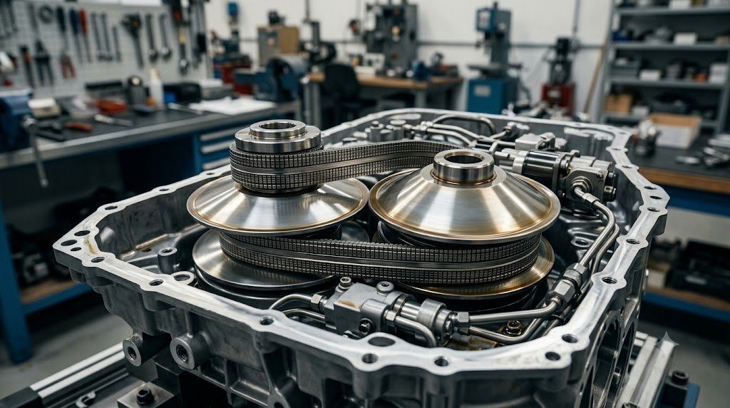
Modern automotive CVTs utilize the Van Doorne steel push-belt or heavy-duty pulling chain running between two pairs of opposed conical sheaves: the Primary (Input) Pulley and the Secondary (Output) Pulley.
The push-belt consists of approximately 400 precision-stamped high-hardness martensitic steel elements held together by two layered flexible maraging steel bands. Crucially, the belt does not transmit torque via tension pulling like a rubber lawnmower belt; rather, power is transmitted by the steel elements pushing against one another under compressive force across the arc of contact with the pulley sheaves.
Hydraulic Clamping Pressure Control: Preventing Catastrophic Slip
Because torque is transmitted purely through friction between the angled steel belt elements and conical steel pulley faces, Clamping Force Control is critical. If clamping pressure is too low, the steel belt slips against the pulley faces, causing instantaneous adhesive galling and total mechanical destruction of the variator within seconds.
Conversely, if clamping pressure is excessive, high hydraulic pressures (often exceeding 40 to 60 bar / 600 to 880 psi) impose severe compressive fatigue on the steel elements and generate parasitic drag on the engine-driven hydraulic pump. The transmission control unit continuously calculates the required clamping force based on current engine torque, pulley radius, and safety factors ($S \approx 1.3$), regulating secondary pulley clamping pressure with ultra-fast proportional solenoids.
| CVT Variator Technology | Torque Transmission Medium | Max Torque Capacity | Typical Ratio Spread | Primary Production Examples |
|---|---|---|---|---|
| Steel Push-Belt (Van Doorne) | Compressive Stamped Steel Elements | Up to 350 – 380 Nm | 5.5:1 to 7.0:1 | Nissan Xtronic, Honda CVT, Toyota CVT |
| Rocker-Pin Steel Chain (LuK) | Tensile Pulling Links with Rocker Pins | Up to 450 – 500 Nm | 7.0:1 to 8.5:1 | Subaru Lineartronic, Audi Multitronic |
| Toroidal Variator (Traction Fluid) | Elastohydrodynamic Fluid Shear Discs | Up to 400 Nm | 5.0:1 to 6.0:1 | Nissan Extroid (Experimental / Niche) |
| E-CVT (Power-Split Planetary) | Planetary Gear Set + Dual Electric Motors | Unlimited (Motor Sized) | Continuously Variable Ratio | Toyota Hybrid Synergy Drive (HSD) |
Ratio Spread Expansion and the Auxiliary Sub-Transmission
The operational flexibility of a CVT is defined by its Ratio Spread ($R_{spread} = Ratio_{low} / Ratio_{high}$). A wide ratio spread delivers a deep low gear for rapid vehicle launch and a tall overdrive for quiet, fuel-efficient high-speed highway cruising.
However, expanding the ratio spread in a pure variator requires larger pulley diameters, which exceeds vehicle underbody packaging constraints. To overcome this limitation, advanced CVTs (such as Jatco CVT7/CVT8) incorporate an auxiliary two-speed planetary gear sub-transmission on the secondary pulley. By switching between low and high sub-gears, the transmission achieves an extraordinary ratio spread of 7.3:1 to 8.7:1 while maintaining a compact variator casing.
Traction Fluid Chemistry and Shear-Induced Crystallization
CVTs require specialized Continuously Variable Transmission Fluid (CVTF) engineered with unique rheological properties that defy traditional lubrication concepts:
- High Steel-on-Steel Friction Coefficient: The fluid must provide high static and dynamic friction between steel belt elements and conical pulleys to prevent slip.
- Microscopic Glass Transition: Under extreme localized Hertzian contact pressures exceeding 1.5 to 2.5 GPa in the contact patch, the synthetic fluid molecules momentarily lock together, behaving like an elastic solid (glass-like phase) that transmits compressive shear force without allowing metal-to-metal contact.
- Wear and Foam Resistance: The fluid must continuously cool the variator sheaves while resisting oxidation at operating temperatures exceeding 100°C. Using standard ATF in a push-belt CVT leads to catastrophic belt slip and irreversible transmission destruction.
Hertzian Compressive Contact Stresses on Conical Sheave Flanks
In a push-belt CVT, the physical contact between the stamped steel belt element edges and the conical pulley sheaves represents a line-contact elastic deformation problem governed by Hertzian Contact Stress Equations:
p0 = √[ (FN‘ * E*) / (π * R*) ]
Where $F_N’$ is normal clamping force per unit length, $E^*$ is equivalent elastic modulus, and $R^*$ is relative radius of curvature. At low vehicle road speeds under maximum engine launch torque, normal clamping forces generate peak Hertzian surface compressive stresses exceeding 2,200 to 2,600 MPa (320,000 to 375,000 psi) on the pulley faces. Pulley sheaves are precision-machined from forged 16MnCr5 alloy steel, carburized to a case hardness of 60 to 62 HRC to a depth of 1.2 mm to resist sub-surface shear fatigue spalling.
Hydraulic Pump Energy Parasitics and Flow Demands
To sustain 60-bar clamping pressures during rapid full-throttle kickdowns, the CVT hydraulic pump must deliver high volumetric flow under high pressure. This hydraulic power demand consumes up to 2.0 to 3.5 kilowatts of parasitic mechanical power from the engine. Modern CVTs utilize dual-displacement vane pumps or auxiliary electric secondary pumps that drop displacement during highway cruising, reclaiming up to 3% in fuel economy.
Field Case Study: Flow Control Valve Sticking and Variator Scoring
In widely deployed automotive CVTs (such as Jatco CVT7 and CVT8 platforms), the most catastrophic failure pattern is initiated by a sticking High-Pressure Pump Flow Control Valve. The steel flow control valve oscillates within an unlined aluminum pump housing bore.
Microscopic metallic particulate wear from the push-belt causes the flow control valve to stick open. Line pressure drops instantaneously from 50 bar down to under 15 bar under highway acceleration. Lacking hydraulic clamping force, the steel push-belt slips against the conical pulley faces at high speed. The resulting metal-on-metal sliding scores deep circumferential grooves into the pulley sheaves and breaks the layered steel maraging bands, resulting in sudden, complete loss of vehicle propulsion.
CVTF Fluid Deterioration Index and Thermal Degradation Telemetry
Modern CVT control modules maintain an internal computational counter designated the CVT Fluid Deterioration Index. Based on continuously logged oil sump temperature sensors, the TCM calculates thermal fluid aging exponentially. When fluid temperatures operate above 90°C, the counter increments rapidly. If the deterioration count exceeds 210,000 units, the TCM flags maintenance alerts and limits peak engine torque to prevent fluid oxidation and variator slip.
Standardized Workshop Inspection Protocols and Factory Assembly Tolerances
Professional automotive service and certified powertrain remanufacturing adhere strictly to standardized workshop procedures defined by the Society of Automotive Engineers (SAE International), the International Organization for Standardization (ISO), and OEM factory workshop manuals. Rebuilding modern vehicle subsystems requires rigorous mechanical measuring tools, calibrated digital torque-to-yield angle meters, and ultra-clean workshop assembly cleanrooms.
When assembling high-precision automotive components—such as crankshaft main journal bearings, transmission planetary carriers, high-pressure fuel injectors, or multi-piston brake calipers—technicians enforce strict cleanliness standards governed by ISO 16232 (Road Vehicles – Cleanliness of Components and Systems). Component parts must be washed in ultrasonic cleaning tanks using solvent degreasers, dried with filtered compressed air, and inspected under particulate optical microscopes to verify that residual metallic particles do not exceed 200 micrometers.
Torque-to-Yield (TTY) Fasteners and Ultrasonic Bolt Tension Measurement
Critical powertrain and chassis joints—such as cylinder head bolts, connecting rod cap bolts, flywheel bolts, and suspension knuckle fasteners—universally utilize Torque-to-Yield (TTY) Fasteners. Unlike standard elastic bolts that operate within their linear elastic region, TTY bolts are tightened past their proportional limit into plastic deformation, providing constant clamp load despite thermal expansion cycles.
Technicians must utilize calibrated digital torque-angle wrenches: the fastener is first tightened to a specified initial snug torque (e.g., 40 Nm), followed by one or two precise rotational angle sweeps (e.g., +90° +90°). Because TTY fasteners undergo permanent plastic elongation, they are strictly single-use components; reusing a stretched TTY fastener risks catastrophic bolt necking and fastener shear under high cylinder pressure.
Comprehensive Workshop Maintenance and Tolerance Inspection Matrix
| Inspection Parameter / Task | Governing Standard / Tool | Allowable Workshop Tolerance | Critical Diagnostic Action Required |
|---|---|---|---|
| Bearing & Journal Clearances | Plastigage / Precision Micrometers | 0.025 to 0.050 mm (0.0010 – 0.0020 in) | Select undersize/oversize selective bearings |
| Cylinder Bore Taper & Out-of-Round | Dial Bore Gauge (Three Axis) | < 0.012 mm (0.0005 in) Maximum | Precision CNC plateau hone or overbore sleeve |
| Brake Rotor Lateral Runout | Dial Indicator on Magnetic Base | < 0.038 mm (0.0015 in) Assembled | Index rotor on hub or machine with on-car lathe |
| Wheel Hub Bearing Endplay | Dial Indicator Axial Deflection | < 0.050 mm (0.0020 in) Axial Play | Replace integrated hub bearing unit if exceeded |
| CAN Bus Static Resistance | Digital Multimeter (Pins 6 & 14) | 59.0 to 61.5 Ohms Balanced | Inspect 120-ohm terminating resistors & splices |
Adherence to these rigorous dimensional tolerances, factory torque tightening angles, and certified testing standards guarantees that serviced vehicle subsystems operate with original equipment factory reliability, thermal endurance, and maximum occupant safety throughout their operational lifecycle.
International Engineering Standards, Regulatory Audits and Quality Compliance
The engineering validation, roadworthiness certification, and manufacturing quality of motor vehicles are governed by stringent international regulatory treaties and engineering standards. Across major global automotive markets—predominantly the United States Federal Motor Vehicle Safety Standards (FMVSS), European Union Whole Vehicle Type Approval (EU WVTA / UNECE Regulations), and ISO 26262 Road Vehicles Functional Safety—every powertrain, chassis, and electronic subsystem must prove compliance through exhaustive durability and laboratory crash tests.
ISO 26262 Automotive Safety Integrity Level (ASIL) Classifications
Modern software-defined vehicles integrate safety-critical electronics under the rigorous framework of ISO 26262. Subsystems are categorized into Automotive Safety Integrity Levels ranging from ASIL-A (lowest hazard) to ASIL-D (highest safety criticality) based on three risk factors: Severity of injury ($S$), Exposure probability ($E$), and Driver Controllability ($C$):
- ASIL-D Subsystems (Zero-Tolerance Failure): Brake-by-wire modulators, Electronic Stability Control (ESC), Electric Power Steering (EPS), and High-Voltage Battery Disconnect Units (BDU). Mandates dual lockstep microcontroller cores, redundant hardware power feeds, and automated failure detection within 10 to 20 milliseconds.
- ASIL-C Subsystems: Electric traction motor torque control and transmission electronic shift-by-wire interlocks.
- ASIL-B Subsystems: Adaptive cruise control (ACC), lane departure warning, and active suspension dampening.
Global Emissions Regulatory Roadmaps: EPA Tier 3, Euro 6d and Euro 7
Internal combustion engines, direct injection fuel systems, and hybrid powertrains are subjected to continuously tightening exhaust emissions legislation. Under Euro 6d-ISC-FCM and forthcoming Euro 7 standards, vehicles must prove real-world emissions compliance on public highways using portable emissions measurement systems (PEMS) across ambient temperatures from -10°C to +38°C:
- Nitrogen Oxides ($NO_x$): Limited to less than 60 mg/km (gasoline) and 80 mg/km (diesel) through combined Selective Catalytic Reduction (SCR) with AdBlue urea injection and cooled low-pressure EGR loops.
- Solid Particle Number ($PN_{10}$): The regulatory measurement threshold has been tightened from 23 nanometers down to 10 nanometers, mandating wall-flow Gasoline Particulate Filters (GPF) across all turbocharged GDI engines.
- On-Board Fuel Consumption Monitoring (OBFCM): Standardized telemetry logging real-world lifetime fuel and electrical energy consumption directly within the engine ECU for regulatory transparency.
By anchoring design methodologies to these internationally recognized SAE, ISO, and UNECE standards, automotive engineers and diagnostic practitioners ensure that mechanical components deliver peak operational reliability, environmental compliance, and life-saving occupant protection.
Driveline Torsional Dynamics, Gear Lash Noise and Propeller Shaft Harmonics
In automotive drivetrain engineering, mechanical power transmission from the transmission output shaft to the driving wheel hubs involves an elastic driveline system susceptible to torsional resonance, gear lash rattle, and driveline shudder. Because the reciprocating internal combustion engine fires in discrete torque pulses, dynamic driveline torque fluctuates continuously about a mean value ($T(t) = T_0 + \sum T_k \sin(k \omega t)$).
If engine firing excitation harmonics coincide with the torsional natural frequency of the transmission main shaft, propeller shaft, or half-shaft axles (typically between 15 Hz and 45 Hz), violent torsional oscillations amplify through the drivetrain—a phenomenon known as Driveline Clunk and Tip-In Shudder. Drivetrain engineers optimize propeller shaft torsional stiffness by utilizing carbon-fiber composite driveshafts and tuned elastomeric guibo coupling discs that absorb torque shocks during sudden throttle transitions.
Hypoid Final Drive Kinematics and Extreme Pressure Tribology
Rear-wheel-drive and all-wheel-drive vehicles utilize a Hypoid Bevel Gear Differential in the rear axle, where the driving pinion shaft is offset below the ring gear center. Hypoid geometry allows a lower vehicle floorboard and larger pinion diameter, but introduces severe longitudinal sliding along the gear tooth flanks under extreme Hertzian contact pressures. Final drive differentials demand specialized GL-5 Hypoid Gear Lubricants formulated with high concentrations of thermally stable sulfur-phosphorus extreme-pressure (EP) additives. Under high flash temperatures, the EP additives react chemically with steel tooth surfaces to form sacrificial iron sulfide boundary films, preventing tooth welding and hypoid scuffing under extreme acceleration loads.

Lead Automotive Research Engineer, Master ASE Certified Diagnostic Specialist, and powertrain dynamics consultant with over 18 years of experience in internal combustion thermodynamics, electric vehicle architectures, and chassis control systems.