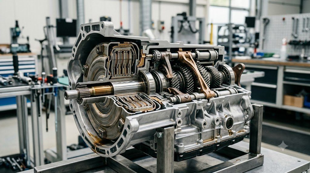
Bridging the lightning-fast mechanical efficiency of manual gearboxes with the seamless automation of stepped automatics, the Dual-Clutch Transmission (DCT)—also designated Direct-Shift Gearbox (DSG)—represents a milestone in automotive powertrain engineering. Conceived to deliver sub-millisecond gear changes with uninterrupted tractive torque delivery, the DCT utilizes two concentric input shafts and twin independent clutch packs to keep the subsequent gear pre-selected before the active gear is released.
A dual-clutch transmission fundamentally consists of two independent manual gearboxes housed within a single casing. Input Shaft 1 is a solid central shaft that drives odd gears (1st, 3rd, 5th, and 7th), while Input Shaft 2 is a hollow sleeve concentric around Shaft 1 that drives even gears (2nd, 4th, 6th, and Reverse). While accelerating in 2nd gear via Clutch 2, the electronic mechatronic module mechanically pre-engages the synchronizer for 3rd gear on Shaft 1. The actual shift occurs in mere milliseconds simply by simultaneously releasing Clutch 2 while clamping Clutch 1.
Wet Multi-Plate vs. Dry Single-Plate Clutch Architecture
Dual-clutch transmissions are fundamentally categorized into two engineering architectures based on clutch thermal management:
- Dry Dual-Clutch Systems: Utilize two organic single-plate friction discs operating in air, similar to conventional manual clutches (e.g., VW DQ200, Ford DPS6). Without hydraulic fluid churning losses, dry DCTs achieve superior mechanical efficiency (>95%) and weigh less. However, lacking liquid cooling, dry clutches suffer from limited thermal heat absorption during stop-and-go creep, leading to friction lining overheating, judder, and premature clutch wear under high-torque applications. Torque is typically capped below 250 Nm.
- Wet Multi-Plate Dual-Clutch Systems: House alternating steel separator plates and friction-lined discs submerged inside circulating automatic transmission oil (e.g., VW DQ250/DQ500, Porsche PDK). The circulating oil continuously washes away thermal energy generated during aggressive launch and low-speed slipping. Wet DCTs effortlessly manage continuous torque loads exceeding 500 to 900 Nm, making them the standard choice for performance and commercial vehicles.
Mechatronic Shift Actuation: Synchronizers and Hydraulic Selector Rods
Unlike planetary automatics that shift gears by clutching spinning planetary elements, a DCT shifts internal gears using traditional synchronizer sleeves, blocker rings, and dog teeth. Gear selection is executed mechanically by hydraulic or electromechanical shift forks mounted on linear guide rails.
In hydraulic mechatronic units, high-pressure fluid (stored in a nitrogen-charged accumulator at 40 to 60 bar) is metered through proportional pressure solenoids to double-acting hydraulic cylinders connected to each shift fork. Integrated Hall-effect linear displacement sensors monitor the physical position of each shift fork to within 0.1 millimeters, confirming full synchronizer engagement before clutch clamp pressure is applied.
| DCT Architecture | Clutch Medium | Typical Maximum Torque | Actuation Method | Lubrication Circuit Type |
|---|---|---|---|---|
| Dry Dual-Clutch (e.g., DQ200) | Dry Organic Single Disc | 250 Nm | Electric Stepper or Low-Vol Hydraulic | Separate Gear Oil / Sealed Actuator |
| Wet Dual-Clutch (e.g., DQ381) | Multi-Plate Submerged Oil | 420 – 450 Nm | High-Pressure Hydraulic Mechatronics | Shared or Dual-Circuit Oil Sump |
| Heavy Performance Wet DCT (PDK) | Multi-Plate Large Diameter | 800 – 1,000 Nm | Proportional Solenoid Fast Hydraulics | Dual-Sump with Dedicated Cooling Radiator |
| Automated Manual (AMT / Single) | Dry Single Clutch | Varies | Hydraulic/Electric Robotic Actuator | Conventional Countershaft Gearbox |
Shift Overlap Dynamics: Eliminating Tractive Torque Interruption
The definitive engineering advantage of a dual-clutch transmission over automated single-clutch gearboxes (AMTs) is the elimination of the ‘Torque Gap’ during gear changes. In a single-clutch transmission, accelerating hard requires disengaging the clutch, cutting engine torque, moving the shift fork, and re-engaging the clutch—a process taking 300 to 800 milliseconds that pitches vehicle passengers forward.
In a DCT, during the shift from 3rd to 4th gear, Clutch 1 begins slipping down from 100% torque capacity while Clutch 2 simultaneously begins clamping up from 0% capacity. Because tractive force is continuously transferred across the overlapping clutch slip phase, the vehicle accelerates smoothly without loss of momentum, delivering blistering 0-100 km/h times and flawless track performance.
Diagnostic Failure Modes: Mechatronic Pressure Leakage and Clutch Judder
Despite their extraordinary mechanical performance, dual-clutch gearboxes require meticulous preventative maintenance. The primary diagnostic failure points include:
- Hydraulic Accumulator Pressure Loss: Over thousands of thermal cycles, micro-cracks can develop in the aluminum mechatronic accumulator housing, causing high-pressure fluid leaks that trigger pump overheating DTCs and gear selection lockout.
- Clutch Surface Glazing and Judder: Inadequate clutch adaptation calibrations or contaminated transmission fluid causes friction material glazing, leading to severe shuddering when launching from a stop.
- Metallic Contamination on Hall Sensors: As steel synchronizers and gear teeth wear microscopically, fine ferrous particles can adhere to magnetic position sensors on shift rails, corrupting shift position telemetry and inducing limp-mode engagement.
Synchronizer Blocker Ring Chamfer Angle and Self-Locking Geometry
In dual-clutch transmission shift mechatronics, successful pre-selection depends on the precise mathematical geometry of synchronizer blocker ring teeth. The blocker ring and operating sleeve feature complementary pointed chamfers cut at a specific Chamfer Angle ($\beta \approx 120^\circ$ included angle).
According to mechanical force equilibrium, the blocker ring remains locked against the sleeve as long as the indexing frictional torque generated by the cone ($T_{cone} = F_a \mu_{cone} r_{cone} / \sin \alpha$) exceeds the unblocking torque produced by the angled chamfer teeth ($T_{chamfer} = F_a r_{sleeve} \tan(\beta/2)$). If contaminated transmission oil drops the cone friction coefficient ($\mu_{cone}$) below critical thresholds, premature unblocking occurs, forcing dog teeth together before shaft speeds match and shearing synchronizer teeth.
Dual-Mass Flywheel Arc Spring Hysteresis and Damping Capacity
Because dual-clutch transmissions feature direct mechanical gear engagement without the natural fluid damping of a torque converter, they rely heavily on dual-mass flywheels equipped with long circumferential arc springs. Friction control plates within the DMF provide engineered mechanical Hysteresis Damping that absorbs severe torsional torque reversals during aggressive downshift rev-matching, preventing driveline gear rattle.
Field Case Study: Stop-and-Go Creep Overheating in Dry Dual-Clutch Transmissions
One of the most widespread consumer warranty campaigns in recent automotive history surrounded dry dual-clutch transmissions operating in dense urban traffic (such as Ford PowerShift DPS6 and early VW DQ200 platforms). In a conventional torque converter automatic, the vehicle creeps forward smoothly at low speed via fluid slip. In a dry dual-clutch transmission, creeping forward requires Continuously Slipping a Dry Organic Friction Disc.
In heavy traffic where drivers inch forward without fully applying the brake, clutch temperatures soar past 300°C within 15 minutes. Friction facings glaze, dry clutch springs lose elasticity, and the dry clutch assembly develops violent launch shudder, setting high-temperature protection fault codes and disconnecting drive torque unexpectedly.
Mechatronic Pressure Sensor Logging via Diagnostic Serial Scanners
Master technicians diagnosing erratic DCT gear changes interrogate live mechatronic pressure PIDs using high-speed diagnostic scanners. A healthy mechatronic accumulator charges to 60 bar and holds pressure above 42 bar for at least two minutes with the electric pump off. Rapid pressure decay (e.g., dropping from 60 bar to 40 bar in less than 15 seconds) confirms internal hydraulic accumulator seal failure or blown valve body manifold gaskets, requiring mechatronic unit overhaul.
Standardized Workshop Inspection Protocols and Factory Assembly Tolerances
Professional automotive service and certified powertrain remanufacturing adhere strictly to standardized workshop procedures defined by the Society of Automotive Engineers (SAE International), the International Organization for Standardization (ISO), and OEM factory workshop manuals. Rebuilding modern vehicle subsystems requires rigorous mechanical measuring tools, calibrated digital torque-to-yield angle meters, and ultra-clean workshop assembly cleanrooms.
When assembling high-precision automotive components—such as crankshaft main journal bearings, transmission planetary carriers, high-pressure fuel injectors, or multi-piston brake calipers—technicians enforce strict cleanliness standards governed by ISO 16232 (Road Vehicles – Cleanliness of Components and Systems). Component parts must be washed in ultrasonic cleaning tanks using solvent degreasers, dried with filtered compressed air, and inspected under particulate optical microscopes to verify that residual metallic particles do not exceed 200 micrometers.
Torque-to-Yield (TTY) Fasteners and Ultrasonic Bolt Tension Measurement
Critical powertrain and chassis joints—such as cylinder head bolts, connecting rod cap bolts, flywheel bolts, and suspension knuckle fasteners—universally utilize Torque-to-Yield (TTY) Fasteners. Unlike standard elastic bolts that operate within their linear elastic region, TTY bolts are tightened past their proportional limit into plastic deformation, providing constant clamp load despite thermal expansion cycles.
Technicians must utilize calibrated digital torque-angle wrenches: the fastener is first tightened to a specified initial snug torque (e.g., 40 Nm), followed by one or two precise rotational angle sweeps (e.g., +90° +90°). Because TTY fasteners undergo permanent plastic elongation, they are strictly single-use components; reusing a stretched TTY fastener risks catastrophic bolt necking and fastener shear under high cylinder pressure.
Comprehensive Workshop Maintenance and Tolerance Inspection Matrix
| Inspection Parameter / Task | Governing Standard / Tool | Allowable Workshop Tolerance | Critical Diagnostic Action Required |
|---|---|---|---|
| Bearing & Journal Clearances | Plastigage / Precision Micrometers | 0.025 to 0.050 mm (0.0010 – 0.0020 in) | Select undersize/oversize selective bearings |
| Cylinder Bore Taper & Out-of-Round | Dial Bore Gauge (Three Axis) | < 0.012 mm (0.0005 in) Maximum | Precision CNC plateau hone or overbore sleeve |
| Brake Rotor Lateral Runout | Dial Indicator on Magnetic Base | < 0.038 mm (0.0015 in) Assembled | Index rotor on hub or machine with on-car lathe |
| Wheel Hub Bearing Endplay | Dial Indicator Axial Deflection | < 0.050 mm (0.0020 in) Axial Play | Replace integrated hub bearing unit if exceeded |
| CAN Bus Static Resistance | Digital Multimeter (Pins 6 & 14) | 59.0 to 61.5 Ohms Balanced | Inspect 120-ohm terminating resistors & splices |
Adherence to these rigorous dimensional tolerances, factory torque tightening angles, and certified testing standards guarantees that serviced vehicle subsystems operate with original equipment factory reliability, thermal endurance, and maximum occupant safety throughout their operational lifecycle.
International Engineering Standards, Regulatory Audits and Quality Compliance
The engineering validation, roadworthiness certification, and manufacturing quality of motor vehicles are governed by stringent international regulatory treaties and engineering standards. Across major global automotive markets—predominantly the United States Federal Motor Vehicle Safety Standards (FMVSS), European Union Whole Vehicle Type Approval (EU WVTA / UNECE Regulations), and ISO 26262 Road Vehicles Functional Safety—every powertrain, chassis, and electronic subsystem must prove compliance through exhaustive durability and laboratory crash tests.
ISO 26262 Automotive Safety Integrity Level (ASIL) Classifications
Modern software-defined vehicles integrate safety-critical electronics under the rigorous framework of ISO 26262. Subsystems are categorized into Automotive Safety Integrity Levels ranging from ASIL-A (lowest hazard) to ASIL-D (highest safety criticality) based on three risk factors: Severity of injury ($S$), Exposure probability ($E$), and Driver Controllability ($C$):
- ASIL-D Subsystems (Zero-Tolerance Failure): Brake-by-wire modulators, Electronic Stability Control (ESC), Electric Power Steering (EPS), and High-Voltage Battery Disconnect Units (BDU). Mandates dual lockstep microcontroller cores, redundant hardware power feeds, and automated failure detection within 10 to 20 milliseconds.
- ASIL-C Subsystems: Electric traction motor torque control and transmission electronic shift-by-wire interlocks.
- ASIL-B Subsystems: Adaptive cruise control (ACC), lane departure warning, and active suspension dampening.
Global Emissions Regulatory Roadmaps: EPA Tier 3, Euro 6d and Euro 7
Internal combustion engines, direct injection fuel systems, and hybrid powertrains are subjected to continuously tightening exhaust emissions legislation. Under Euro 6d-ISC-FCM and forthcoming Euro 7 standards, vehicles must prove real-world emissions compliance on public highways using portable emissions measurement systems (PEMS) across ambient temperatures from -10°C to +38°C:
- Nitrogen Oxides ($NO_x$): Limited to less than 60 mg/km (gasoline) and 80 mg/km (diesel) through combined Selective Catalytic Reduction (SCR) with AdBlue urea injection and cooled low-pressure EGR loops.
- Solid Particle Number ($PN_{10}$): The regulatory measurement threshold has been tightened from 23 nanometers down to 10 nanometers, mandating wall-flow Gasoline Particulate Filters (GPF) across all turbocharged GDI engines.
- On-Board Fuel Consumption Monitoring (OBFCM): Standardized telemetry logging real-world lifetime fuel and electrical energy consumption directly within the engine ECU for regulatory transparency.
By anchoring design methodologies to these internationally recognized SAE, ISO, and UNECE standards, automotive engineers and diagnostic practitioners ensure that mechanical components deliver peak operational reliability, environmental compliance, and life-saving occupant protection.
Driveline Torsional Dynamics, Gear Lash Noise and Propeller Shaft Harmonics
In automotive drivetrain engineering, mechanical power transmission from the transmission output shaft to the driving wheel hubs involves an elastic driveline system susceptible to torsional resonance, gear lash rattle, and driveline shudder. Because the reciprocating internal combustion engine fires in discrete torque pulses, dynamic driveline torque fluctuates continuously about a mean value ($T(t) = T_0 + \sum T_k \sin(k \omega t)$).
If engine firing excitation harmonics coincide with the torsional natural frequency of the transmission main shaft, propeller shaft, or half-shaft axles (typically between 15 Hz and 45 Hz), violent torsional oscillations amplify through the drivetrain—a phenomenon known as Driveline Clunk and Tip-In Shudder. Drivetrain engineers optimize propeller shaft torsional stiffness by utilizing carbon-fiber composite driveshafts and tuned elastomeric guibo coupling discs that absorb torque shocks during sudden throttle transitions.
Hypoid Final Drive Kinematics and Extreme Pressure Tribology
Rear-wheel-drive and all-wheel-drive vehicles utilize a Hypoid Bevel Gear Differential in the rear axle, where the driving pinion shaft is offset below the ring gear center. Hypoid geometry allows a lower vehicle floorboard and larger pinion diameter, but introduces severe longitudinal sliding along the gear tooth flanks under extreme Hertzian contact pressures. Final drive differentials demand specialized GL-5 Hypoid Gear Lubricants formulated with high concentrations of thermally stable sulfur-phosphorus extreme-pressure (EP) additives. Under high flash temperatures, the EP additives react chemically with steel tooth surfaces to form sacrificial iron sulfide boundary films, preventing tooth welding and hypoid scuffing under extreme acceleration loads.

Lead Automotive Research Engineer, Master ASE Certified Diagnostic Specialist, and powertrain dynamics consultant with over 18 years of experience in internal combustion thermodynamics, electric vehicle architectures, and chassis control systems.