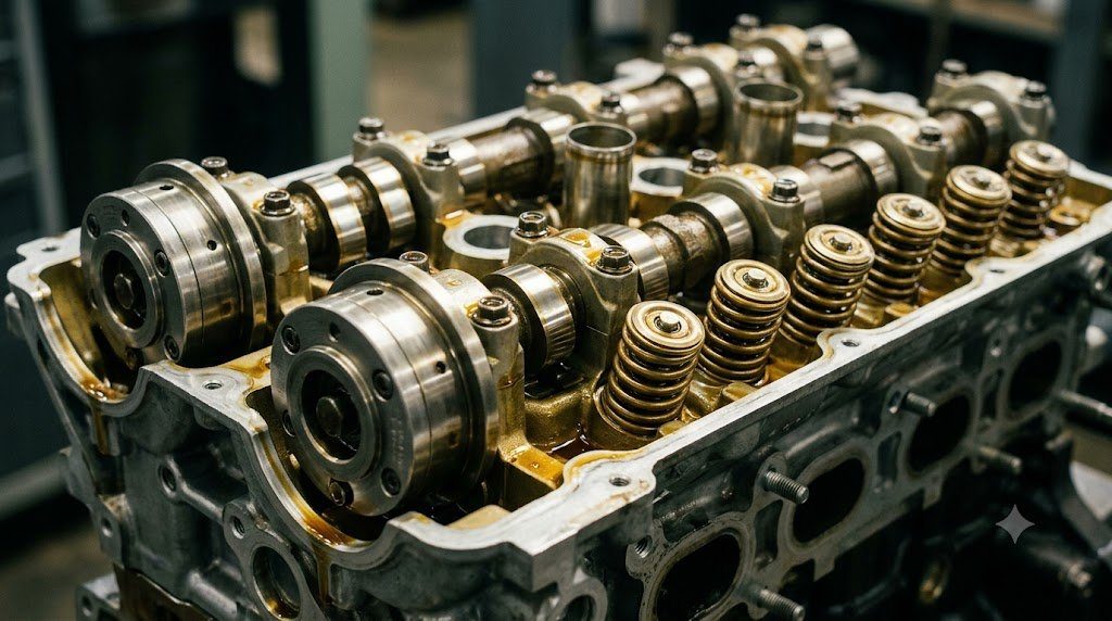
The valvetrain of an internal combustion engine governs the breathing capacity of its cylinders, dictating volumetric efficiency ($\eta_v$), gas exchange pumping losses, internal exhaust gas recirculation (EGR), and high-RPM power limits. While early automotive engines relied on fixed camshaft profiles that represented an uneasy compromise between smooth idle stability and high-RPM power delivery, modern powertrains employ active Variable Valve Timing (VVT) and Variable Valve Lift (VVL) systems to continuously adapt intake and exhaust valve events in real time across the engine operating map.
A high-performance fixed camshaft designed for peak horsepower features long opening duration (280°+ of crank angle) and substantial valve overlap (the period where both intake and exhaust valves remain open simultaneously at TDC). At low idle speeds (750 RPM), high overlap induces exhaust gas reversion into the intake manifold, causing severe cyclic combustion instability, rough idling, and high unburned hydrocarbon emissions. Conversely, a mild camshaft designed for smooth idling starves the engine of airflow above 5,000 RPM, choking high-end torque.
Hydraulic Cam Phasers: Vane-Type Actuation and Closed-Loop Control
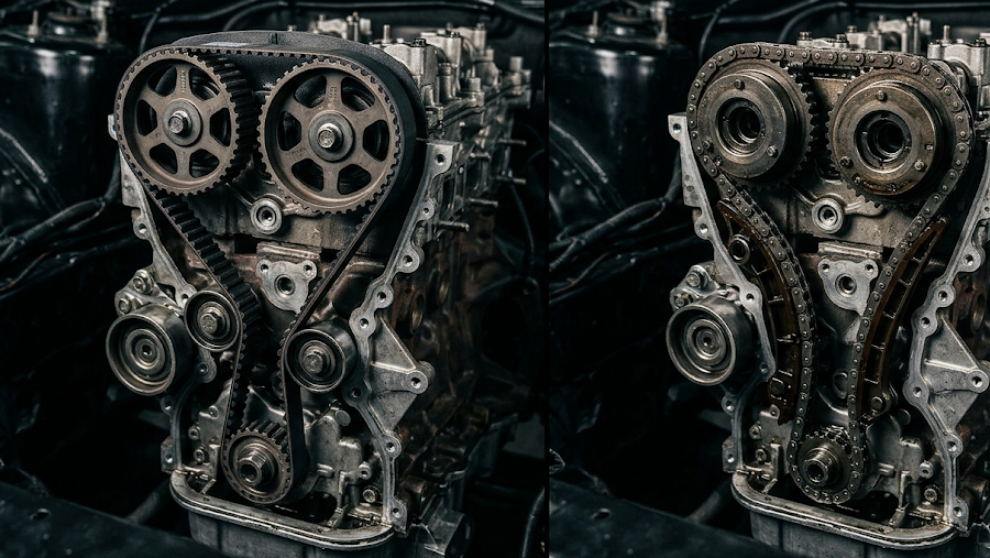
The most widespread form of variable valve timing is the Hydraulic Vane-Type Cam Phaser, mounted directly onto the snout of the camshaft in place of a rigid timing sprocket. Pressurized engine oil from the main oil galley is metered through a camshaft-mounted Oil Control Valve (OCV)—a pulse-width modulated electromagnetic proportional solenoid—into internal advancing or retarding chambers within the phaser rotor.
By regulating oil pressure across the internal vanes, the ECU can shift the camshaft centerline by up to 40 to 60 crankshaft degrees relative to the crankshaft. Closed-loop feedback is maintained by high-resolution Hall-effect camshaft position sensors reading multi-tooth reluctor wheels, allowing the engine controller to achieve target phase angles within fractions of a second.
Internal Exhaust Gas Recirculation (EGR) via Valve Overlap
Beyond adjusting intake air timing, dual-independent cam phasing (independent control of both intake and exhaust camshafts) enables Internal EGR. During medium-load suburban driving, the ECU advances intake valve opening and retards exhaust valve closing, creating a wide valve overlap window at Top Dead Center.
Rather than relying on an external, cloggable EGR pipe and valve, inert exhaust gas is drawn directly back into the cylinder bore. This inert gas dilutes the incoming fresh charge, lowering peak combustion flame temperatures below the 1,800 K threshold where toxic Nitrogen Oxides ($NO_x$) form, while simultaneously reducing engine pumping work by raising manifold absolute pressure.
| Valvetrain System | Adjustment Parameter | Mechanical Actuator Type | Dynamic Response Speed | Notable Production Implementation |
|---|---|---|---|---|
| Hydraulic Vane Cam Phaser | Phase Timing (Advance/Retard) | Proportional Oil Solenoid | 15 – 25 deg/sec (Oil Temp Dependent) | Toyota VVT-i, Ford Ti-VCT |
| Electric Motor Cam Phaser | Phase Timing (Full Range) | Brushless DC Planetary Drive | 50 – 100 deg/sec (Instantaneous at Cold Start) | Lexus VVT-iE, Honda VTC |
| Multi-Lobe Cam Switching | Discrete Duration & Lift | Hydraulic Locking Pin on Rocker | Single Cam Cycle Transition | Honda VTEC, Mitsubishi MIVEC |
| Continuous Variable Lift | Continuous Valve Lift (0.2-10mm) | Eccentric Shaft Servo Actuator | 0.2 sec from Min to Max Lift | BMW Valvetronic, Nissan VVEL |
Continuous Variable Valve Lift: Eliminating the Throttle Butterfly
While cam phasing adjusts the timing of when valves open, it cannot modify the maximum physical lift or duration of the valve opening event. Advanced powertrains utilize Continuous Variable Valve Lift (VVL) systems—exemplified by BMW’s Valvetronic and Nissan’s VVEL—to control engine airflow purely via intake valve lift, rendering the conventional intake throttle plate obsolete during normal operation.
In Valvetronic systems, an electronically controlled eccentric shaft alters the fulcrum pivot point of an intermediate rocker arm situated between the camshaft lobe and the roller finger follower. By rotating the eccentric shaft via an electric stepper motor, the maximum valve lift can be continuously varied from a microscopic 0.18 mm (for ultra-smooth idle) to 9.9 mm (for wide-open throttle).
Dynamic Valve Spring Float and Harmonic Surge Frequencies
At high rotational speeds (6,500 to 9,000 RPM), the valvetrain is subjected to violent kinetic accelerations exceeding 1,000 g. If the closing acceleration of the cam profile exceeds the restoring spring force of the valve spring, the roller follower loses physical contact with the cam lobe—a catastrophic kinematic failure termed Valve Float.
Furthermore, standard cylindrical valve springs exhibit natural harmonic surge frequencies. If valvetrain operating harmonics align with the spring’s natural frequency, internal surging causes coils to clash, inducing severe spring fatigue fractures. Modern engines employ progressive-pitch beehive springs and oval-wire cross-sections that disrupt internal harmonic standing waves, providing superior valve seating control at extreme engine speeds.
Cam Lobe Kinematic Acceleration Profiles: SVAJ Derivatives and Valve TOSS
The geometric profile of an automotive camshaft lobe is governed by higher-order calculus. Valvetrain designers map valve motion across four successive mathematical derivatives: Displacement ($S$), Velocity ($V$), Acceleration ($A$), and Jerk ($J$). Abrupt discontinuities in the jerk curve (the derivative of acceleration: $J = \frac{da}{dt}$) excite high-frequency structural resonances in the pushrod or rocker arm, causing severe valvetrain clatter and accelerated roller follower spalling.
At high engine speeds, positive cam acceleration must transition smoothly into deceleration. If the valve deceleration rate exceeds the restoring spring force divided by valvetrain moving mass ($a_{dec} > F_{spring} / m_{eff}$), the roller follower separates from the cam nose—an event termed Valve Toss. When the follower violently crashes back down onto the cam flank, localized Hertzian contact stresses exceed 2,500 MPa, causing instantaneous lobe spalling and fractured rocker arms.
Oil Aeration and Hydraulic Lash Adjuster (HLA) Deflation Dynamics
Modern variable valvetrains rely on Hydraulic Lash Adjusters (HLAs / hydraulic lifters) to maintain zero clearance between follower and valve stem. However, under sustained high-RPM operation, oil sloshing in the oil pan can aerate motor oil with entrained microscopic air bubbles. Because air is compressible, aerated oil causes internal HLA check-valves to compress (‘pump-down’), reducing actual valve lift by up to 2.0 mm, inducing severe power loss, and creating loud valvetrain tapping noises.
Field Case Study: Cam Phaser Sludge Seizure and Timing Retard Correlation
In modern variable valve timing engines, engine oil functions not merely as a lubricant; it is the vital hydraulic working fluid of the valvetrain. A prevalent failure pattern across modern variable valvetrains is Hydraulic Cam Phaser Sludge Seizure caused by degraded motor oil and extended maintenance intervals.
Thermal breakdown bakes engine oil into sticky carbon varnish inside the microscopic (0.03 mm) clearances of the phaser rotor vanes and Oil Control Valve (OCV) spool passages. When the ECU commands cam timing advance, the stuck phaser cannot move. The camshaft position sensor detects an angular discrepancy between target and actual timing, setting persistent correlation DTCs (e.g., P0011 / P0016 Cam/Crank Correlation Bank 1).
Dual-Channel Lab-Scope Verification of Cam and Crank Phasing Signals
Verifying VVT operational health without disassembling engine timing covers requires simultaneous dual-channel oscilloscope logging of the Crankshaft Position (CKP) sensor on Channel A and Camshaft Position (CMP) sensor on Channel B. By counting crankshaft reluctor pulses between the missing tooth gap and the primary camshaft sync pulse, technicians measure actual angular phase shift in real time as the throttle is revved, pinpointing sluggish phaser movement or stretched timing chains instantly.
Standardized Workshop Inspection Protocols and Factory Assembly Tolerances
Professional automotive service and certified powertrain remanufacturing adhere strictly to standardized workshop procedures defined by the Society of Automotive Engineers (SAE International), the International Organization for Standardization (ISO), and OEM factory workshop manuals. Rebuilding modern vehicle subsystems requires rigorous mechanical measuring tools, calibrated digital torque-to-yield angle meters, and ultra-clean workshop assembly cleanrooms.
When assembling high-precision automotive components—such as crankshaft main journal bearings, transmission planetary carriers, high-pressure fuel injectors, or multi-piston brake calipers—technicians enforce strict cleanliness standards governed by ISO 16232 (Road Vehicles – Cleanliness of Components and Systems). Component parts must be washed in ultrasonic cleaning tanks using solvent degreasers, dried with filtered compressed air, and inspected under particulate optical microscopes to verify that residual metallic particles do not exceed 200 micrometers.
Torque-to-Yield (TTY) Fasteners and Ultrasonic Bolt Tension Measurement
Critical powertrain and chassis joints—such as cylinder head bolts, connecting rod cap bolts, flywheel bolts, and suspension knuckle fasteners—universally utilize Torque-to-Yield (TTY) Fasteners. Unlike standard elastic bolts that operate within their linear elastic region, TTY bolts are tightened past their proportional limit into plastic deformation, providing constant clamp load despite thermal expansion cycles.
Technicians must utilize calibrated digital torque-angle wrenches: the fastener is first tightened to a specified initial snug torque (e.g., 40 Nm), followed by one or two precise rotational angle sweeps (e.g., +90° +90°). Because TTY fasteners undergo permanent plastic elongation, they are strictly single-use components; reusing a stretched TTY fastener risks catastrophic bolt necking and fastener shear under high cylinder pressure.
Comprehensive Workshop Maintenance and Tolerance Inspection Matrix
| Inspection Parameter / Task | Governing Standard / Tool | Allowable Workshop Tolerance | Critical Diagnostic Action Required |
|---|---|---|---|
| Bearing & Journal Clearances | Plastigage / Precision Micrometers | 0.025 to 0.050 mm (0.0010 – 0.0020 in) | Select undersize/oversize selective bearings |
| Cylinder Bore Taper & Out-of-Round | Dial Bore Gauge (Three Axis) | < 0.012 mm (0.0005 in) Maximum | Precision CNC plateau hone or overbore sleeve |
| Brake Rotor Lateral Runout | Dial Indicator on Magnetic Base | < 0.038 mm (0.0015 in) Assembled | Index rotor on hub or machine with on-car lathe |
| Wheel Hub Bearing Endplay | Dial Indicator Axial Deflection | < 0.050 mm (0.0020 in) Axial Play | Replace integrated hub bearing unit if exceeded |
| CAN Bus Static Resistance | Digital Multimeter (Pins 6 & 14) | 59.0 to 61.5 Ohms Balanced | Inspect 120-ohm terminating resistors & splices |
Adherence to these rigorous dimensional tolerances, factory torque tightening angles, and certified testing standards guarantees that serviced vehicle subsystems operate with original equipment factory reliability, thermal endurance, and maximum occupant safety throughout their operational lifecycle.
International Engineering Standards, Regulatory Audits and Quality Compliance
The engineering validation, roadworthiness certification, and manufacturing quality of motor vehicles are governed by stringent international regulatory treaties and engineering standards. Across major global automotive markets—predominantly the United States Federal Motor Vehicle Safety Standards (FMVSS), European Union Whole Vehicle Type Approval (EU WVTA / UNECE Regulations), and ISO 26262 Road Vehicles Functional Safety—every powertrain, chassis, and electronic subsystem must prove compliance through exhaustive durability and laboratory crash tests.
ISO 26262 Automotive Safety Integrity Level (ASIL) Classifications
Modern software-defined vehicles integrate safety-critical electronics under the rigorous framework of ISO 26262. Subsystems are categorized into Automotive Safety Integrity Levels ranging from ASIL-A (lowest hazard) to ASIL-D (highest safety criticality) based on three risk factors: Severity of injury ($S$), Exposure probability ($E$), and Driver Controllability ($C$):
- ASIL-D Subsystems (Zero-Tolerance Failure): Brake-by-wire modulators, Electronic Stability Control (ESC), Electric Power Steering (EPS), and High-Voltage Battery Disconnect Units (BDU). Mandates dual lockstep microcontroller cores, redundant hardware power feeds, and automated failure detection within 10 to 20 milliseconds.
- ASIL-C Subsystems: Electric traction motor torque control and transmission electronic shift-by-wire interlocks.
- ASIL-B Subsystems: Adaptive cruise control (ACC), lane departure warning, and active suspension dampening.
Global Emissions Regulatory Roadmaps: EPA Tier 3, Euro 6d and Euro 7
Internal combustion engines, direct injection fuel systems, and hybrid powertrains are subjected to continuously tightening exhaust emissions legislation. Under Euro 6d-ISC-FCM and forthcoming Euro 7 standards, vehicles must prove real-world emissions compliance on public highways using portable emissions measurement systems (PEMS) across ambient temperatures from -10°C to +38°C:
- Nitrogen Oxides ($NO_x$): Limited to less than 60 mg/km (gasoline) and 80 mg/km (diesel) through combined Selective Catalytic Reduction (SCR) with AdBlue urea injection and cooled low-pressure EGR loops.
- Solid Particle Number ($PN_{10}$): The regulatory measurement threshold has been tightened from 23 nanometers down to 10 nanometers, mandating wall-flow Gasoline Particulate Filters (GPF) across all turbocharged GDI engines.
- On-Board Fuel Consumption Monitoring (OBFCM): Standardized telemetry logging real-world lifetime fuel and electrical energy consumption directly within the engine ECU for regulatory transparency.
By anchoring design methodologies to these internationally recognized SAE, ISO, and UNECE standards, automotive engineers and diagnostic practitioners ensure that mechanical components deliver peak operational reliability, environmental compliance, and life-saving occupant protection.
Combustion Chamber Fluid Mechanics, Tumble Flow and Thermodynamic Boundary Layers
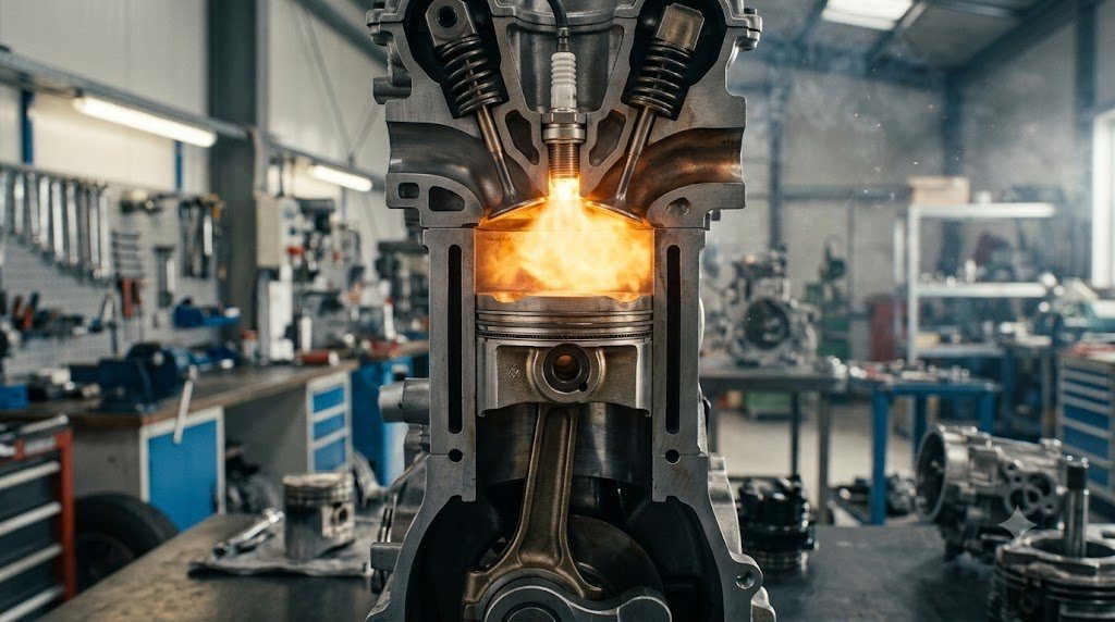
In the thermodynamic optimization of internal combustion engines, the geometric architecture of the cylinder head combustion roof exerts direct control over flame propagation speed and thermal heat losses. Modern direct-injection four-valve pent-roof combustion chambers are engineered to generate high-velocity Intake Tumble Flow—a coherent barrel-shaped vortex of air rotating perpendicularly to the cylinder axis.
As the piston accelerates upward on the compression stroke toward Top Dead Center, geometric squish pads on the piston crown compress this large tumble vortex, breaking it down into a cascade of fine, high-intensity microscopic turbulent eddies. This microscopic turbulence increases the Turbulent Flame Speed ($u_t$) by a factor of four compared to laminar flame speeds ($u_l$), completing combustion in fewer crank angle degrees and allowing significant spark retard reduction.
Piston Ring Tribology and Blow-by Hermetic Gas Sealing
Reciprocating pistons rely on three precision-engineered piston rings running inside plateau-honed cylinder liners to maintain gas hermetic sealing while controlling oil consumption: the Top Compression Ring, the Second Scraper Ring, and the Three-Piece Oil Control Ring. The top compression ring—manufactured from nodular cast iron or stainless steel with physical vapor deposition (PVD) diamond-like carbon (DLC) coatings—utilizes cylinder gas combustion pressure entering behind the ring groove to force the ring face tightly against the cylinder wall. Minimizing blow-by past the ring gaps to under 15 to 25 liters per minute prevents crankcase pressurization, preserves oil quality, and eliminates hydrocarbon emissions leakage.

Lead Automotive Research Engineer, Master ASE Certified Diagnostic Specialist, and powertrain dynamics consultant with over 18 years of experience in internal combustion thermodynamics, electric vehicle architectures, and chassis control systems.