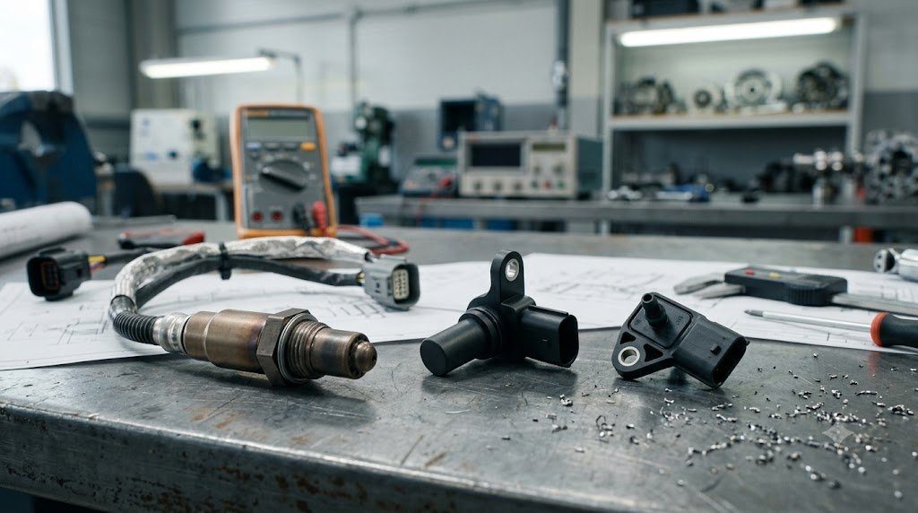
An electronic control unit is only as capable as the precision and fidelity of its sensory inputs. Modern motor vehicles rely on an array of dozens of specialized Automotive Sensors that convert mechanical displacements, rotational velocities, fluid pressures, thermal states, and exhaust gas chemical concentrations into calibrated electrical voltages and digital pulses. These sensors operate across diverse physical transduction principles: electromagnetic Hall effect, semiconductor piezoresistive strain, and electrochemical zirconia Nernstian ion transport.
Automotive sensors operate under severe physical constraints: 12V electrical noise spikes, under-hood ground voltage offsets, and extreme thermal gradients (-40°C to +150°C). High-precision sensors incorporate integrated application-specific integrated circuits (ASICs) directly within the sensor housing to perform analog-to-digital conversion, thermal temperature compensation, and active digital filtering before transmitting telemetry to the main ECU.
Hall-Effect and Magneto-Resistive Speed and Position Sensors
Precise measurement of crankshaft rotational angle (for spark and fuel timing), camshaft phase angle, and transmission shaft speed relies on Hall-Effect and Anisotropic Magneto-Resistive (AMR) Sensors. When an electrical current flows through a thin semiconductor slab exposed to an orthogonal magnetic field ($B$), the Lorentz force deflects charge carriers to one side, generating a measurable transverse voltage: the Hall Voltage ($V_H \propto I B / d$).
In a differential Hall sensor reading a missing-tooth reluctor wheel (e.g., 60-2 tooth trigger wheel on the crankshaft):
- As a ferromagnetic reluctor tooth passes the sensor face, it concentrates magnetic flux from a permanent internal back-biasing magnet, triggering an internal Schmitt trigger comparator.
- The sensor outputs a clean 0-5V digital square wave with sharp rise and fall times (<1 μs).
- The two missing teeth represent a 12-degree reference gap that allows the ECU to establish exact Top Dead Center (TDC) of cylinder number one within a single engine revolution.
Piezoresistive Transduction: MAP, Rail Pressure and In-Cylinder Sensing
Measurement of dynamic fluid pressures—ranging from Manifold Absolute Pressure (MAP: 0.2 to 3.0 bar absolute) to Gasoline Direct Injection fuel rails (up to 350 bar) and diesel common-rail lines (up to 2,500 bar)—relies on Piezoresistive Micro-Electro-Mechanical Systems (MEMS).
A MEMS pressure sensor incorporates a microscopic silicon diaphragm with four integrated piezoresistive resistors configured in a balanced Wheatstone Bridge Circuit:
- Fluid pressure mechanically flexes the microscopic silicon diaphragm.
- Deflection alters the interatomic spacing in the silicon crystal lattice, altering its electrical resistivity (piezoresistive effect).
- The bridge unbalances, producing a differential millivolt output signal directly proportional to applied pressure.
- Internal ASIC amplifiers calibrate and amplify this voltage into an industry-standard 0.5V (minimum pressure) to 4.5V (maximum pressure) linear analog sweep.
| Automotive Sensor Type | Transduction Physical Principle | Output Signal Format | Key Operating Range | Critical Diagnostic Failure Mode |
|---|---|---|---|---|
| Crankshaft Position (CKP) | Hall Effect / AMR Reluctance | Digital 0-5V Square Wave Pulse | 0 to 8,000+ RPM | Thermal Intermittent Signal Drop (Engine Stall) |
| Manifold Absolute Pressure (MAP) | Piezoresistive MEMS Diaphragm | Analog 0.5V – 4.5V Linear Sweep | 20 to 350 kPa Absolute | Vacuum Port Carbon Plugging / Signal Drift |
| Wideband Air-Fuel Ratio (AFR) | Zirconia Oxygen Ion Pump Cell | Variable Current (±mA Pump) | λ = 0.65 to ∞ (Free Air) | Heater Circuit Burnout / Silicon Contamination |
| Mass Airflow (Hot-Wire MAF) | Thermal Convective Heat Dissipation | Analog Voltage / Digital Frequency | 0 to 1,200 kg/hr Airflow | Contaminated Platinum Wire (Oil/Dirt Film) |
Wideband Oxygen Sensors: Zirconia Nernst Cell and Electrochemical Ion Pumping
While legacy ‘narrowband’ oxygen sensors acted as crude chemical switches capable only of detecting whether exhaust was rich or lean of stoichiometry (switching between 0.1V and 0.9V at $\lambda = 1.0$), modern direct-injection powertrains require continuous measurement across the entire spectrum. This is accomplished via Planar Wideband Air-Fuel Ratio Sensors (LSU 4.9).
A wideband sensor incorporates two distinct electrochemical elements operating inside a miniature diffusion chamber heated to 750°C:
- Nernst Reference Cell: Measures oxygen concentration relative to ambient air.
- Electrochemical Oxygen Pump Cell: An electronic control circuit pumps oxygen ions into or out of the diffusion chamber to maintain the Nernst cell constantly at exactly 450 mV ($\lambda = 1.00$).
- Current Measurement: The exact electrical current (measured in milliamperes, $\pm I_{pump}$) required to pump oxygen ions to maintain balance is directly proportional to the air-fuel ratio. Negative pump current indicates rich exhaust; positive pump current indicates lean exhaust.
Sensor Ground Loops and Analog Signal Degradation
Because analog sensors output delicate 0.5V to 4.5V signals, even 100 millivolts of voltage drop across a deteriorated chassis ground terminal introduces a 2.5% error in measured fuel pressure or coolant temperature. Automotive ECUs isolate sensitive sensors using dedicated Clean Sensor Ground Circuits (Signal Return) that bypass dirty vehicle chassis metal entirely.
Master technicians diagnosing intermittent drivability faults must always measure sensor reference voltage (5.00V ± 0.05V) and sensor return ground resistance directly at the sensor harness connector with the system under electrical load.
SENT Protocol (SAE J2716): High-Speed Digital Single-Wire Telemetry
To eliminate analog sensor signal degradation and ground offset errors entirely, modern automotive throttle bodies, rail pressure sensors, and mass airflow meters have transitioned to the SENT Protocol (Single Edge Nibble Transmission – SAE J2716).
SENT is a unidirectional digital protocol that encodes data within the precise time duration between consecutive falling edges of a 5V digital signal transmitted over a single wire. Data is transmitted in 4-bit nibbles calibrated against an initial synchronization calibration pulse. SENT sensors provide 12-bit to 16-bit measurement resolution, transmit integrated temperature telemetry across secondary nibbles, and include automated checksum CRC verification, eliminating analog ADC conversion errors.
Nernst Equation and Wideband Sensor Pumping Cell Electrochemistry
The electrochemical reference cell within a wideband oxygen sensor generates an electromotive force governed by the Nernst Equation:
E = (R * T) / (4 * F) * ln( PO2,ref / PO2,exhaust )
Where $R$ is the universal gas constant, $F$ is Faraday’s constant, and $P_{O2}$ represents partial oxygen pressures. Under lean exhaust conditions ($P_{O2,exhaust}$ high), the Nernst voltage drops. The ASIC feedback circuit responds by driving positive current into the electrochemical oxygen pump cell, transporting oxygen ions ($O^{2-}$) out of the diffusion gap until the Nernst voltage returns to exactly 450 mV. The required pump current ($I_{pump}$) provides a direct, linear measurement of exhaust oxygen concentration.
Field Case Study: 5-Volt Reference Circuit Short to Ground and Sensor Pull-Down
In modern powertrain electronic architectures, the ECU generates a highly stabilized 5.00V Reference Circuit (V_REF) internally, distributing it across multiple analog sensors: Accelerator Pedal Sensors, MAP sensor, Fuel Rail Pressure sensor, and A/C Pressure transducer.
A notorious diagnostic trap occurs when a single sensor wiring harness chafes against the engine block or exhaust manifold, shorting the 5V reference wire to chassis ground. Because multiple critical sensors share the same internal V_REF power rail, the voltage across all connected sensors collapses to 0.0V. The ECU logs simultaneous fault codes for every sensor on the circuit, while the throttle stops responding completely. Technicians must disconnect sensors sequentially while monitoring V_REF with a digital multimeter until 5.00V is restored, isolating the pinched harness wire.
Oscilloscope In-Cylinder Pressure Transducer Waveform Signatures
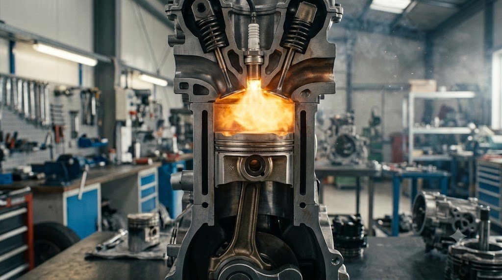
Advanced diagnostic technicians utilize specialized laboratory pressure transducers (such as Pico WPS500X) threaded directly into a spark plug hole on a running or cranking engine. Oscilloscope pressure waveforms display physical combustion chamber events: exhaust valve opening points, exhaust stroke backpressure (revealing restricted catalytic converters exceeding 0.3 bar backpressure), and intake valve opening timing, allowing non-intrusive mechanical timing verification without removing timing covers.
Standardized Workshop Inspection Protocols and Factory Assembly Tolerances
Professional automotive service and certified powertrain remanufacturing adhere strictly to standardized workshop procedures defined by the Society of Automotive Engineers (SAE International), the International Organization for Standardization (ISO), and OEM factory workshop manuals. Rebuilding modern vehicle subsystems requires rigorous mechanical measuring tools, calibrated digital torque-to-yield angle meters, and ultra-clean workshop assembly cleanrooms.
When assembling high-precision automotive components—such as crankshaft main journal bearings, transmission planetary carriers, high-pressure fuel injectors, or multi-piston brake calipers—technicians enforce strict cleanliness standards governed by ISO 16232 (Road Vehicles – Cleanliness of Components and Systems). Component parts must be washed in ultrasonic cleaning tanks using solvent degreasers, dried with filtered compressed air, and inspected under particulate optical microscopes to verify that residual metallic particles do not exceed 200 micrometers.
Torque-to-Yield (TTY) Fasteners and Ultrasonic Bolt Tension Measurement
Critical powertrain and chassis joints—such as cylinder head bolts, connecting rod cap bolts, flywheel bolts, and suspension knuckle fasteners—universally utilize Torque-to-Yield (TTY) Fasteners. Unlike standard elastic bolts that operate within their linear elastic region, TTY bolts are tightened past their proportional limit into plastic deformation, providing constant clamp load despite thermal expansion cycles.
Technicians must utilize calibrated digital torque-angle wrenches: the fastener is first tightened to a specified initial snug torque (e.g., 40 Nm), followed by one or two precise rotational angle sweeps (e.g., +90° +90°). Because TTY fasteners undergo permanent plastic elongation, they are strictly single-use components; reusing a stretched TTY fastener risks catastrophic bolt necking and fastener shear under high cylinder pressure.
Comprehensive Workshop Maintenance and Tolerance Inspection Matrix
| Inspection Parameter / Task | Governing Standard / Tool | Allowable Workshop Tolerance | Critical Diagnostic Action Required |
|---|---|---|---|
| Bearing & Journal Clearances | Plastigage / Precision Micrometers | 0.025 to 0.050 mm (0.0010 – 0.0020 in) | Select undersize/oversize selective bearings |
| Cylinder Bore Taper & Out-of-Round | Dial Bore Gauge (Three Axis) | < 0.012 mm (0.0005 in) Maximum | Precision CNC plateau hone or overbore sleeve |
| Brake Rotor Lateral Runout | Dial Indicator on Magnetic Base | < 0.038 mm (0.0015 in) Assembled | Index rotor on hub or machine with on-car lathe |
| Wheel Hub Bearing Endplay | Dial Indicator Axial Deflection | < 0.050 mm (0.0020 in) Axial Play | Replace integrated hub bearing unit if exceeded |
| CAN Bus Static Resistance | Digital Multimeter (Pins 6 & 14) | 59.0 to 61.5 Ohms Balanced | Inspect 120-ohm terminating resistors & splices |
Adherence to these rigorous dimensional tolerances, factory torque tightening angles, and certified testing standards guarantees that serviced vehicle subsystems operate with original equipment factory reliability, thermal endurance, and maximum occupant safety throughout their operational lifecycle.
International Engineering Standards, Regulatory Audits and Quality Compliance
The engineering validation, roadworthiness certification, and manufacturing quality of motor vehicles are governed by stringent international regulatory treaties and engineering standards. Across major global automotive markets—predominantly the United States Federal Motor Vehicle Safety Standards (FMVSS), European Union Whole Vehicle Type Approval (EU WVTA / UNECE Regulations), and ISO 26262 Road Vehicles Functional Safety—every powertrain, chassis, and electronic subsystem must prove compliance through exhaustive durability and laboratory crash tests.
ISO 26262 Automotive Safety Integrity Level (ASIL) Classifications
Modern software-defined vehicles integrate safety-critical electronics under the rigorous framework of ISO 26262. Subsystems are categorized into Automotive Safety Integrity Levels ranging from ASIL-A (lowest hazard) to ASIL-D (highest safety criticality) based on three risk factors: Severity of injury ($S$), Exposure probability ($E$), and Driver Controllability ($C$):
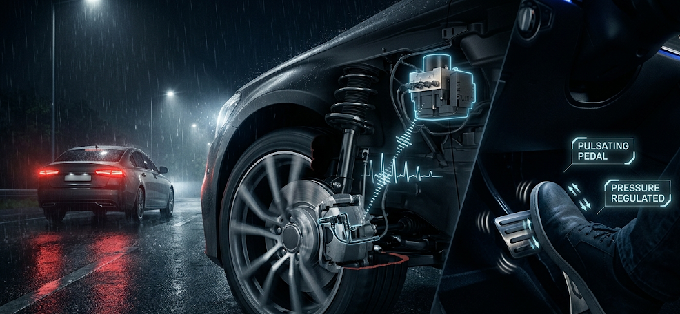
- ASIL-D Subsystems (Zero-Tolerance Failure): Brake-by-wire modulators, Electronic Stability Control (ESC), Electric Power Steering (EPS), and High-Voltage Battery Disconnect Units (BDU). Mandates dual lockstep microcontroller cores, redundant hardware power feeds, and automated failure detection within 10 to 20 milliseconds.
- ASIL-C Subsystems: Electric traction motor torque control and transmission electronic shift-by-wire interlocks.
- ASIL-B Subsystems: Adaptive cruise control (ACC), lane departure warning, and active suspension dampening.
Global Emissions Regulatory Roadmaps: EPA Tier 3, Euro 6d and Euro 7
Internal combustion engines, direct injection fuel systems, and hybrid powertrains are subjected to continuously tightening exhaust emissions legislation. Under Euro 6d-ISC-FCM and forthcoming Euro 7 standards, vehicles must prove real-world emissions compliance on public highways using portable emissions measurement systems (PEMS) across ambient temperatures from -10°C to +38°C:
- Nitrogen Oxides ($NO_x$): Limited to less than 60 mg/km (gasoline) and 80 mg/km (diesel) through combined Selective Catalytic Reduction (SCR) with AdBlue urea injection and cooled low-pressure EGR loops.
- Solid Particle Number ($PN_{10}$): The regulatory measurement threshold has been tightened from 23 nanometers down to 10 nanometers, mandating wall-flow Gasoline Particulate Filters (GPF) across all turbocharged GDI engines.
- On-Board Fuel Consumption Monitoring (OBFCM): Standardized telemetry logging real-world lifetime fuel and electrical energy consumption directly within the engine ECU for regulatory transparency.
By anchoring design methodologies to these internationally recognized SAE, ISO, and UNECE standards, automotive engineers and diagnostic practitioners ensure that mechanical components deliver peak operational reliability, environmental compliance, and life-saving occupant protection.
Automotive Microcontroller Flash Bootloaders and Cyber-Security Architecture
As modern vehicles transition into Software-Defined Vehicles (SDVs) receiving regular Firmware Over-The-Air (FOTA) updates, the security and integrity of electronic control unit software has become a paramount safety imperative. Automotive microcontrollers integrate dedicated Hardware Security Modules (HSM) featuring isolated cryptographic processing cores and secure hardware keystores.
When an ECU powers on, the internal Primary Bootloader executes a Secure Boot Sequence. The bootloader calculates an SHA-256 cryptographic hash across the application flash memory and verifies it against the vehicle manufacturer’s asymmetric digital public key certificate (RSA-2048 or ECC-256). If aftermarket tuning software, corrupted firmware, or unauthorized third-party code is detected, the HSM rejects the application image, preventing tampered software from executing on critical vehicle steering, braking, or powertrain networks.
Electromagnetic Compatibility (EMC) and CISPR 25 Vehicle Standards
Under-hood electronic control units and sensor harnesses must comply with strict CISPR 25 Class 5 Electromagnetic Compatibility (EMC) standards. Switch-mode DC-DC converters, high-voltage inverters, and PWM ignition coils generate intense conducted and radiated high-frequency radio frequency noise (from 150 kHz AM band up to 2.5 GHz Wi-Fi/Bluetooth frequencies). ECUs utilize multi-layer printed circuit boards (PCBs) with internal continuous ground planes, ferrite bead common-mode chokes on I/O lines, and die-cast aluminum enclosures acting as Faraday cages to ensure electromagnetic shielding.

Lead Automotive Research Engineer, Master ASE Certified Diagnostic Specialist, and powertrain dynamics consultant with over 18 years of experience in internal combustion thermodynamics, electric vehicle architectures, and chassis control systems.