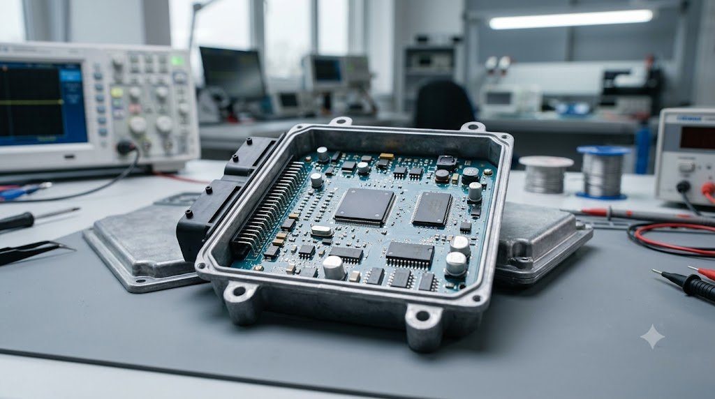
The modern automotive Engine Control Unit (ECU / ECM) is an industrial real-time embedded supercomputer tasked with managing hundreds of dynamic physical parameters simultaneously. Operating within an under-hood environment subjected to extreme thermal cycling (-40°C to +125°C), high electrical noise transients, and severe engine vibrations, the ECU executes millions of computational operations per second to regulate fuel injector pulse widths down to microseconds, calculate ignition spark timing to within fractions of a crankshaft degree, and modulate turbocharger boost pressure via closed-loop Proportional-Integral-Derivative (PID) control algorithms.
Unlike a personal computer or smartphone operating system where brief milliseconds of computational stutter represent minor UI latency, an automotive powertrain ECU operates under Hard Real-Time Deterministic Constraints. If an engine is spinning at 6,000 RPM, a complete engine revolution takes merely 10 milliseconds. Missing an ignition coil dwell cutoff calculation by just 0.5 milliseconds can result in catastrophic spark detonation, melting a forged piston crown within seconds.
Microcontroller Core Architecture: 32-Bit Lockstep Automotive Silicon
Modern automotive ECUs are built around specialized 32-bit automotive multicore microcontrollers (such as Infineon TriCore AURIX or NXP S32G series) manufactured to ISO 26262 ASIL-D functional safety specifications. Key architectural blocks include:
- Dual or Triple Lockstep Cores: Redundant processing cores execute identical instruction sets in cycle-by-cycle synchronization; internal hardware comparators trigger an interrupt trap if memory corruption or silicon bit-flips occur.
- Time Processing Units (TPU / GTM – Generic Timer Module): Dedicated coprocessors that handle time-critical, angle-based engine events (crankshaft reluctor tooth counting, injector firing pulses, and coil charging) independently of the main CPU cores, freeing primary processing power for complex model-based thermodynamic equations.
- Hardware Flash and Calibration RAM: High-reliability non-volatile memory storing base fueling volumetric efficiency (VE) lookup tables, spark advance maps, and diagnostic fault thresholds.
Stoichiometry and Closed-Loop Fueling: Short-Term vs. Long-Term Fuel Trims
To ensure high efficiency and allow 3-way catalytic converters to oxidize Carbon Monoxide ($CO$) and Unburned Hydrocarbons ($HC$) while simultaneously reducing Nitrogen Oxides ($NO_x$), the engine must maintain an exact stoichiometric fuel-air ratio of 14.7:1 by mass (Lambda $\lambda = 1.00$) for pure gasoline.
The ECU achieves this via closed-loop feedback monitoring pre-catalytic wideband oxygen sensors (Air-Fuel Ratio sensors):
- Short-Term Fuel Trim (STFT): A rapid, real-time dynamic adjustment that pulses injector duration up and down by ±1% to ±25% several times per second, compensating for instantaneous airflow variations.
- Long-Term Fuel Trim (LTFT): Learned adaptive fuel corrections stored in non-volatile memory across various engine load/RPM cells. If a persistent vacuum leak or clogged fuel injector forces STFT to remain elevated at +15% over minutes of driving, the ECU increments LTFT to compensate permanently. If total trim ($STFT + LTFT$) exceeds calibration limits (typically ±20% to ±25%), diagnostic trouble codes P0171 (System Too Lean) or P0172 (System Too Rich) are flagged.
| ECU Control Subsystem | Primary Feedback Sensor | Mathematical Control Mechanism | Update Execution Frequency | Safety Redundancy |
|---|---|---|---|---|
| Fuel Injection Timing | Crankshaft + Camshaft Hall Sensors | Speed-Density & Mass Airflow Model | Every Cylinder Event (Angle-Based) | Dual Cam Reluctor Verification |
| Closed-Loop AFR Regulation | Pre-Cat Wideband Lambda Sensor | Proportional-Integral (PI) Trims | 10 – 20 ms Feedback Loop | Sensor Heater Circuit Monitoring |
| Electronic Throttle (Drive-by-Wire) | Dual Redundant Accelerator Potentiometers | Closed-Loop DC Motor H-Bridge | 1 – 2 ms Fast Loop | Dual Inverted Output Signals (TPS1/TPS2) |
| Wastegate Boost Pressure | Manifold Absolute Pressure (MAP) | Closed-Loop PID Frequency Solenoid | 10 ms Time-Based Loop | Overboost Fuel Cut Emergency Strategy |
Drive-by-Wire Electronic Throttle Control (ETC) Safety Architectures
Legacy mechanical throttle cables connecting the gas pedal directly to the throttle body have been universally replaced by Drive-by-Wire (ETC). The driver’s pedal incorporates dual redundant sensors (APP1 and APP2) outputting inverse or staggered voltage sweeps (e.g., APP1 sweeps 0.5V to 4.5V while APP2 sweeps 0.25V to 2.25V).
The ECU continuously compares the two pedal sensor signals. If a broken wire, dirty potentiometer contact, or short circuit causes the two signals to disagree by more than 5%, the ECU immediately cuts power to the throttle body H-bridge drive motor. Heavy internal return springs snap the throttle plate closed to an engineered ‘fail-safe high-idle’ position (1,200 RPM), allowing the vehicle to limp safely off the roadway without runaway acceleration.
PID Wastegate Modulation: Taming Turbocharger Boost Creep and Spool
Regulating boost pressure on high-performance turbocharged engines requires dynamic feedback control. Modern ECUs utilize a Proportional-Integral-Derivative (PID) algorithm to modulate the duty cycle of an electronic wastegate control solenoid or rotary servo actuator:
- Proportional Gain ($P$): Produces an immediate control response proportional to current boost error ($Target – Actual$). Drives rapid wastegate closure during initial spool-up.
- Integral Gain ($I$): Accumulates past steady-state error over time, steadily adjusting duty cycle to eliminate minor offsets and hold target boost precisely during extended wide-open-throttle pulls.
- Derivative Gain ($D$): Anticipates future boost spikes by reacting to the rate of pressure rise ($\frac{dP}{dt}$), cracking the wastegate slightly before target boost is reached to prevent aggressive overshoot and spark knock.
Speed-Density vs. Mass Airflow (MAF) Air Mass Calculation Algorithms
The core computational task of an engine ECU is establishing the mass of trapped air ($m_{air}$) within each cylinder to calculate exact fuel mass injection ($m_{fuel} = m_{air} / AFR_{target}$). Modern ECUs utilize two primary airflow modeling algorithms:
- Direct Mass Airflow (MAF): Directly measures air mass entering the throttle body via a hot-wire anemometer sensor. Highly accurate under steady-state conditions, but suffers from acoustic reversion pulsation errors under aggressive camshaft overlap.
- Speed-Density Model: Calculates cylinder air charge via the Ideal Gas Law: $m_{air} = \frac{P_{intake} V_d}{R T_{intake}} \cdot \eta_v(RPM, P_{intake})$. The ECU interpolates a massive 3D Volumetric Efficiency (VE) Table indexed by engine RPM and Manifold Absolute Pressure. Speed-density delivers instantaneous transient response during rapid throttle stomps before intake airflow has fully stabilized.
Knock Sensor Piezoelectric Bandpass Filtering and Individual Cylinder Retard
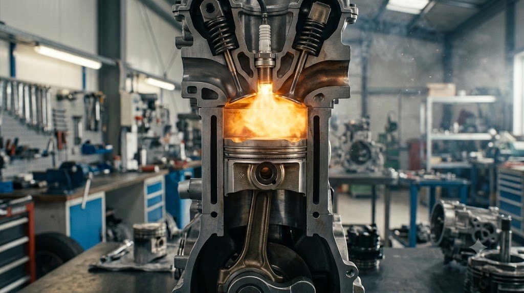
To protect engines operating at maximum boost, piezoceramic accelerometer knock sensors bolted to the engine block sample acoustic engine vibrations. When cylinder detonation occurs, explosive pressure oscillations generate characteristic high-frequency acoustic ringing between 5.5 kHz and 7.2 kHz. The ECU’s digital signal processor (DSP) bandpass filters this frequency window: if vibration amplitude exceeds background baseline thresholds, the ECU instantly retards spark advance by 3 to 5 degrees exclusively on the knocking cylinder, recovering timing progressively over subsequent firing cycles.
Field Case Study: Unmetered False Air Leaks and Fuel Trim Divergence
When diagnosing persistent check engine lights with Lean DTCs (P0171 / P0174), novice technicians frequently replace oxygen sensors prematurely. A rigorous master diagnostic approach utilizes freeze-frame fuel trim data analysis:
If Long-Term Fuel Trim (LTFT) is elevated to +22% at idle speed (750 RPM) but drops progressively to a healthy +3% at highway cruise (2,500 RPM under load), the fault is mathematically proven to be a Vacuum Leak (Unmetered False Air) downstream of the Mass Airflow sensor (such as cracked PCV hoses or leaking intake manifold gaskets). At idle, the volume of unmetered air entering through the crack represents a large percentage of total intake air, driving trims lean. At high RPM, total engine airflow is massive, rendering the small vacuum leak negligible and allowing fuel trims to normalize.
Automotive Smoke Machine Evaporative and Vacuum Diagnostic Testing
Locating microscopic intake vacuum leaks and EVAP fuel vapor leaks requires introducing pressurized synthetic smoke vapor (generated from mineral oil vaporized with inert nitrogen gas) into the intake tract at 0.5 psi. Technicians illuminate the engine bay with high-intensity ultraviolet (UV) inspection lights; fluorescent dye embedded within the escaping smoke illuminates exact leak pathways instantly, pinpointing deteriorated gaskets without guessing.
Standardized Workshop Inspection Protocols and Factory Assembly Tolerances
Professional automotive service and certified powertrain remanufacturing adhere strictly to standardized workshop procedures defined by the Society of Automotive Engineers (SAE International), the International Organization for Standardization (ISO), and OEM factory workshop manuals. Rebuilding modern vehicle subsystems requires rigorous mechanical measuring tools, calibrated digital torque-to-yield angle meters, and ultra-clean workshop assembly cleanrooms.
When assembling high-precision automotive components—such as crankshaft main journal bearings, transmission planetary carriers, high-pressure fuel injectors, or multi-piston brake calipers—technicians enforce strict cleanliness standards governed by ISO 16232 (Road Vehicles – Cleanliness of Components and Systems). Component parts must be washed in ultrasonic cleaning tanks using solvent degreasers, dried with filtered compressed air, and inspected under particulate optical microscopes to verify that residual metallic particles do not exceed 200 micrometers.
Torque-to-Yield (TTY) Fasteners and Ultrasonic Bolt Tension Measurement
Critical powertrain and chassis joints—such as cylinder head bolts, connecting rod cap bolts, flywheel bolts, and suspension knuckle fasteners—universally utilize Torque-to-Yield (TTY) Fasteners. Unlike standard elastic bolts that operate within their linear elastic region, TTY bolts are tightened past their proportional limit into plastic deformation, providing constant clamp load despite thermal expansion cycles.
Technicians must utilize calibrated digital torque-angle wrenches: the fastener is first tightened to a specified initial snug torque (e.g., 40 Nm), followed by one or two precise rotational angle sweeps (e.g., +90° +90°). Because TTY fasteners undergo permanent plastic elongation, they are strictly single-use components; reusing a stretched TTY fastener risks catastrophic bolt necking and fastener shear under high cylinder pressure.
Comprehensive Workshop Maintenance and Tolerance Inspection Matrix
| Inspection Parameter / Task | Governing Standard / Tool | Allowable Workshop Tolerance | Critical Diagnostic Action Required |
|---|---|---|---|
| Bearing & Journal Clearances | Plastigage / Precision Micrometers | 0.025 to 0.050 mm (0.0010 – 0.0020 in) | Select undersize/oversize selective bearings |
| Cylinder Bore Taper & Out-of-Round | Dial Bore Gauge (Three Axis) | < 0.012 mm (0.0005 in) Maximum | Precision CNC plateau hone or overbore sleeve |
| Brake Rotor Lateral Runout | Dial Indicator on Magnetic Base | < 0.038 mm (0.0015 in) Assembled | Index rotor on hub or machine with on-car lathe |
| Wheel Hub Bearing Endplay | Dial Indicator Axial Deflection | < 0.050 mm (0.0020 in) Axial Play | Replace integrated hub bearing unit if exceeded |
| CAN Bus Static Resistance | Digital Multimeter (Pins 6 & 14) | 59.0 to 61.5 Ohms Balanced | Inspect 120-ohm terminating resistors & splices |
Adherence to these rigorous dimensional tolerances, factory torque tightening angles, and certified testing standards guarantees that serviced vehicle subsystems operate with original equipment factory reliability, thermal endurance, and maximum occupant safety throughout their operational lifecycle.
International Engineering Standards, Regulatory Audits and Quality Compliance
The engineering validation, roadworthiness certification, and manufacturing quality of motor vehicles are governed by stringent international regulatory treaties and engineering standards. Across major global automotive markets—predominantly the United States Federal Motor Vehicle Safety Standards (FMVSS), European Union Whole Vehicle Type Approval (EU WVTA / UNECE Regulations), and ISO 26262 Road Vehicles Functional Safety—every powertrain, chassis, and electronic subsystem must prove compliance through exhaustive durability and laboratory crash tests.
ISO 26262 Automotive Safety Integrity Level (ASIL) Classifications
Modern software-defined vehicles integrate safety-critical electronics under the rigorous framework of ISO 26262. Subsystems are categorized into Automotive Safety Integrity Levels ranging from ASIL-A (lowest hazard) to ASIL-D (highest safety criticality) based on three risk factors: Severity of injury ($S$), Exposure probability ($E$), and Driver Controllability ($C$):
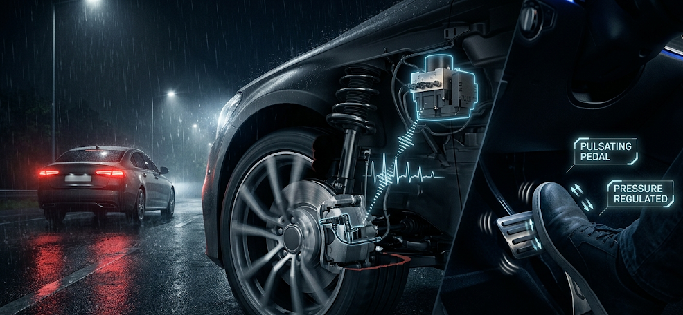
- ASIL-D Subsystems (Zero-Tolerance Failure): Brake-by-wire modulators, Electronic Stability Control (ESC), Electric Power Steering (EPS), and High-Voltage Battery Disconnect Units (BDU). Mandates dual lockstep microcontroller cores, redundant hardware power feeds, and automated failure detection within 10 to 20 milliseconds.
- ASIL-C Subsystems: Electric traction motor torque control and transmission electronic shift-by-wire interlocks.
- ASIL-B Subsystems: Adaptive cruise control (ACC), lane departure warning, and active suspension dampening.
Global Emissions Regulatory Roadmaps: EPA Tier 3, Euro 6d and Euro 7
Internal combustion engines, direct injection fuel systems, and hybrid powertrains are subjected to continuously tightening exhaust emissions legislation. Under Euro 6d-ISC-FCM and forthcoming Euro 7 standards, vehicles must prove real-world emissions compliance on public highways using portable emissions measurement systems (PEMS) across ambient temperatures from -10°C to +38°C:
- Nitrogen Oxides ($NO_x$): Limited to less than 60 mg/km (gasoline) and 80 mg/km (diesel) through combined Selective Catalytic Reduction (SCR) with AdBlue urea injection and cooled low-pressure EGR loops.
- Solid Particle Number ($PN_{10}$): The regulatory measurement threshold has been tightened from 23 nanometers down to 10 nanometers, mandating wall-flow Gasoline Particulate Filters (GPF) across all turbocharged GDI engines.
- On-Board Fuel Consumption Monitoring (OBFCM): Standardized telemetry logging real-world lifetime fuel and electrical energy consumption directly within the engine ECU for regulatory transparency.
By anchoring design methodologies to these internationally recognized SAE, ISO, and UNECE standards, automotive engineers and diagnostic practitioners ensure that mechanical components deliver peak operational reliability, environmental compliance, and life-saving occupant protection.
Automotive Microcontroller Flash Bootloaders and Cyber-Security Architecture
As modern vehicles transition into Software-Defined Vehicles (SDVs) receiving regular Firmware Over-The-Air (FOTA) updates, the security and integrity of electronic control unit software has become a paramount safety imperative. Automotive microcontrollers integrate dedicated Hardware Security Modules (HSM) featuring isolated cryptographic processing cores and secure hardware keystores.
When an ECU powers on, the internal Primary Bootloader executes a Secure Boot Sequence. The bootloader calculates an SHA-256 cryptographic hash across the application flash memory and verifies it against the vehicle manufacturer’s asymmetric digital public key certificate (RSA-2048 or ECC-256). If aftermarket tuning software, corrupted firmware, or unauthorized third-party code is detected, the HSM rejects the application image, preventing tampered software from executing on critical vehicle steering, braking, or powertrain networks.
Electromagnetic Compatibility (EMC) and CISPR 25 Vehicle Standards
Under-hood electronic control units and sensor harnesses must comply with strict CISPR 25 Class 5 Electromagnetic Compatibility (EMC) standards. Switch-mode DC-DC converters, high-voltage inverters, and PWM ignition coils generate intense conducted and radiated high-frequency radio frequency noise (from 150 kHz AM band up to 2.5 GHz Wi-Fi/Bluetooth frequencies). ECUs utilize multi-layer printed circuit boards (PCBs) with internal continuous ground planes, ferrite bead common-mode chokes on I/O lines, and die-cast aluminum enclosures acting as Faraday cages to ensure electromagnetic shielding.

Lead Automotive Research Engineer, Master ASE Certified Diagnostic Specialist, and powertrain dynamics consultant with over 18 years of experience in internal combustion thermodynamics, electric vehicle architectures, and chassis control systems.