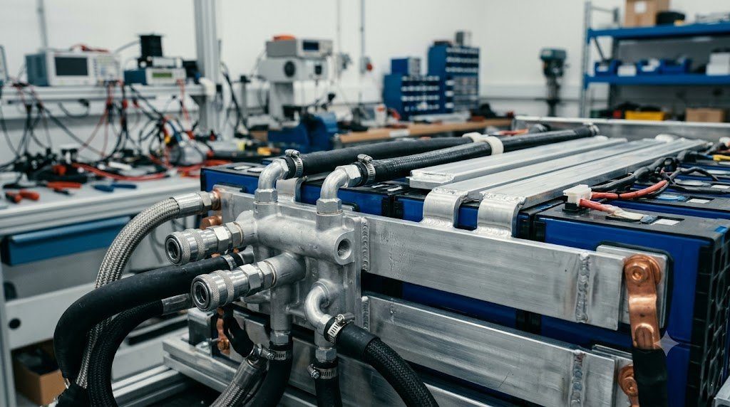
The operational lifespan, fast-charging speed, driving range, and safety of a modern electric vehicle are governed entirely by its Battery Thermal Management System (BTMS). Lithium-ion traction cells function within an exceptionally narrow ideal thermal window—strictly between 20°C and 35°C (68°F to 95°F). Temperatures below 0°C severely restrict charging rates and trigger lithium plating, while temperatures above 50°C dramatically accelerate electrochemical solid electrolyte interphase (SEI) growth, permanently degrading cell capacity. Modern BTMS architectures utilize liquid cooling cold plates, refrigerant heat pumps, and cutting-edge immersion cooling to manage extreme thermal transients.
Operating a traction battery outside its thermal sweet spot carries severe penalties: for every 10°C increase in average operating temperature above 35°C, cell aging rates double according to the Arrhenius relation ($k = A e^{-E_a / R T}$). Conversely, charging a freezing battery (<0°C) forces lithium ions to plate onto the graphite anode as metallic lithium spikes rather than intercalating smoothly, destroying cell capacity and risking internal short circuits.
Liquid Cold Plate Architectures: Bottom Cooling vs. Inter-Cell Serpentine Bands
Modern automotive battery packs predominantly utilize liquid coolant loops circulating an inhibited ethylene glycol-water mixture (50/50 ratio) through specialized aluminum heat exchangers:
- Bottom Cooling Cold Plates: Used extensively with prismatic and pouch cells. Extruded aluminum plates with internal multi-port fluid micro-channels are positioned beneath the cell modules. High-thermal-conductivity gap pads (TIM – Thermal Interface Material) fill microscopic air voids between cell can bottoms and the aluminum plate, transferring heat via conduction.
- Serpentine Inter-Cell Cooling Ribbons: Popularized by Tesla for cylindrical cells (18650, 2170, and 4680 formats). Narrow extruded aluminum fluid channels snake between adjacent cell rows, making direct contact with the cylindrical cell can sides. Because cylindrical cells conduct heat significantly faster radially out their side walls than axially out their bases, serpentine side cooling provides superior thermal uniformity ($< 2^\circ\text{C}$ temperature delta across the cell body).
Extreme DC Fast Charging Thermal Loads: Sizing Cooling Capacity
The most demanding thermal challenge confronting an electric vehicle is not high-speed highway cruising; it is Extreme Fast Charging (XFC at 250 to 350 kW). When a 100 kWh battery charges from 10% to 80% in 20 minutes, internal cell resistance ($R_{int}$) dissipates continuous heat governed by Joule’s law ($P_{heat} = I^2 R_{int}$):
Pheat = (500 A)2 * 0.04 Ω = 10,000 Watts (10 kW of Continuous Heat)
The vehicle’s thermal management system must evacuate up to 10 to 15 kilowatts of thermal energy continuously while keeping all individual cells strictly below 45°C. To achieve this, the vehicle’s air conditioning compressor is commanded into high-speed chilling mode, routing refrigerant through a plate heat exchanger (Chiller) to sub-cool the battery glycol loop to 10°C before entering the pack.
| Cooling Architecture Topology | Thermal Medium | Convective Heat Transfer Coeff (h) | System Complexity | Cooling Uniformity |
|---|---|---|---|---|
| Passive / Forced Air Cooling | Ambient Air Flow | 20 – 100 W/m²·K | Lowest (Obsolescent) | Poor (Severe Thermal Gradients) |
| Indirect Liquid Cold Plate | Ethylene Glycol / Water 50/50 | 1,000 – 3,000 W/m²·K | Moderate (Industry Standard) | Good (±3°C Cell-to-Cell Delta) |
| Direct Dielectric Immersion | Synthetic Dielectric Hydrocarbon Fluid | 5,000 – 10,000 W/m²·K | High (Specialized Sealing) | Exceptional (±1°C Delta) |
| Two-Phase Refrigerant Boiling | Direct R-1234yf or CO2 Evaporation | 8,000 – 15,000 W/m²·K | High (High-Pressure Piping) | Outstanding Phase Change Latent Heat |
Integrated Heat Pump Thermal Loops: Multi-Port Octovalve Integration
In cold winter climates (-10°C to -20°C), an electric vehicle cannot rely on engine waste heat to warm the passenger cabin and condition the battery pack. Utilizing resistive electric PTC heaters drains significant battery power, cutting winter driving range by up to 35% to 40%.
Modern electric vehicles deploy Multi-Source Heat Pump Systems (such as Tesla’s Octovalve architecture). Controlled by rotary multi-port coolant selector valves, the heat pump scavenges waste heat from every onboard electrical component—inverter SiC switches, electric traction motor stators, onboard chargers, and battery cells—and pumps that thermal energy into the passenger cabin, recovering up to 3 kilowatts of heat for every 1 kilowatt of electrical compressor power consumed (Coefficient of Performance $COP \approx 2.5 \text{ to } 3.5$).
Next-Generation Direct Immersion Cooling: Submerged Battery Architectures
To push fast charging beyond 350 kW toward 500 kW without thermal bottlenecking, motorsport hypercars and next-generation EVs are pioneering Dielectric Immersion Cooling. Instead of isolating coolant inside aluminum cold plates, non-conductive synthetic dielectric fluids (such as engineered polyalphaolefins or fluorinated liquids) are pumped directly across bare cell terminals and battery casing surfaces.
Direct fluid contact eliminates all thermal resistance interfaces (gap pads and metal casings), providing complete 360-degree thermal enveloping of every cell. Immersion cooling virtually eliminates cell-to-cell temperature gradients and acts as an inherent fire suppressant, suffocating localized thermal runaway events before they can propagate across the pack.
Navier-Stokes Microchannel Computational Fluid Dynamics (CFD)
The design of automotive battery cooling cold plates relies on solving coupled Navier-Stokes Hydrodynamic and Energy Equations:
ρ (u • ∇) u = -∇p + μ ∇²u | ρ Cp (u • ∇) T = k ∇²T + Φ
Engineers optimize internal micro-channel geometry to balance convective heat transfer ($Nu = f(Re, Pr)$) against hydraulic pressure drop ($\Delta P$). If channel hydraulic resistance is excessive, coolant pump power consumption climbs past 500 Watts, draining battery range. Modern cold plates utilize parallel dimpled flow distributors that induce controlled micro-vortex turbulence, maximizing convective heat transfer coefficients while maintaining coolant pressure drops under 35 kPa.
Dielectric Fluid Breakdown Voltage and Material Compatibility
In direct immersion-cooled battery systems, dielectric fluids must maintain electrical insulation at breakdown potentials exceeding > 40 kV / 2.5 mm. Furthermore, the fluid must exhibit strict chemical compatibility with cell seal polymers, busbar epoxies, and silicone gaskets, preventing plasticizer leaching and long-term chemical swelling that could compromise battery enclosure hermetic sealing.
Field Case Study: Coolant Crossover Leaks and Low-Conductivity Glycol Standards
In liquid-cooled electric vehicle battery packs, aluminum cold plates run in close physical proximity to high-voltage busbars and cell terminals. If a brazed cold plate joint develops a microscopic pinhole fracture due to road vibration fatigue, ethylene glycol coolant sprays directly into the battery pack enclosure.
Traditional automotive engine coolant is highly conductive due to ionic corrosion inhibitors; spraying standard coolant onto 400V battery terminals would trigger violent electrical arcing, localized short circuits, and instantaneous thermal runaway. For this reason, all electrified vehicle manufacturers mandate specialized Low-Conductivity EV Coolant (such as BASF Glysantin G30-EV). Formulated with non-ionic organic acid inhibitors, low-conductivity coolant maintains an electrical conductivity below 100 μS/cm, preventing electrical short-circuiting even if an internal coolant leak occurs.
Automated Battery Pack Coolant Vacuum-Decay Pressure Leak Testing
Whenever an EV battery pack is disassembled for cell module service, resealing the enclosure requires certified leak testing. Technicians connect a calibrated diagnostic vacuum pump to the pack test port, drawing the enclosure to -50 mbar vacuum. The system must maintain vacuum for 15 minutes with less than 0.5 mbar pressure decay, guaranteeing complete IP67 hermetic sealing against road flood water intrusion before the vehicle is returned to service.
Standardized Workshop Inspection Protocols and Factory Assembly Tolerances
Professional automotive service and certified powertrain remanufacturing adhere strictly to standardized workshop procedures defined by the Society of Automotive Engineers (SAE International), the International Organization for Standardization (ISO), and OEM factory workshop manuals. Rebuilding modern vehicle subsystems requires rigorous mechanical measuring tools, calibrated digital torque-to-yield angle meters, and ultra-clean workshop assembly cleanrooms.
When assembling high-precision automotive components—such as crankshaft main journal bearings, transmission planetary carriers, high-pressure fuel injectors, or multi-piston brake calipers—technicians enforce strict cleanliness standards governed by ISO 16232 (Road Vehicles – Cleanliness of Components and Systems). Component parts must be washed in ultrasonic cleaning tanks using solvent degreasers, dried with filtered compressed air, and inspected under particulate optical microscopes to verify that residual metallic particles do not exceed 200 micrometers.
Torque-to-Yield (TTY) Fasteners and Ultrasonic Bolt Tension Measurement
Critical powertrain and chassis joints—such as cylinder head bolts, connecting rod cap bolts, flywheel bolts, and suspension knuckle fasteners—universally utilize Torque-to-Yield (TTY) Fasteners. Unlike standard elastic bolts that operate within their linear elastic region, TTY bolts are tightened past their proportional limit into plastic deformation, providing constant clamp load despite thermal expansion cycles.
Technicians must utilize calibrated digital torque-angle wrenches: the fastener is first tightened to a specified initial snug torque (e.g., 40 Nm), followed by one or two precise rotational angle sweeps (e.g., +90° +90°). Because TTY fasteners undergo permanent plastic elongation, they are strictly single-use components; reusing a stretched TTY fastener risks catastrophic bolt necking and fastener shear under high cylinder pressure.
Comprehensive Workshop Maintenance and Tolerance Inspection Matrix
| Inspection Parameter / Task | Governing Standard / Tool | Allowable Workshop Tolerance | Critical Diagnostic Action Required |
|---|---|---|---|
| Bearing & Journal Clearances | Plastigage / Precision Micrometers | 0.025 to 0.050 mm (0.0010 – 0.0020 in) | Select undersize/oversize selective bearings |
| Cylinder Bore Taper & Out-of-Round | Dial Bore Gauge (Three Axis) | < 0.012 mm (0.0005 in) Maximum | Precision CNC plateau hone or overbore sleeve |
| Brake Rotor Lateral Runout | Dial Indicator on Magnetic Base | < 0.038 mm (0.0015 in) Assembled | Index rotor on hub or machine with on-car lathe |
| Wheel Hub Bearing Endplay | Dial Indicator Axial Deflection | < 0.050 mm (0.0020 in) Axial Play | Replace integrated hub bearing unit if exceeded |
| CAN Bus Static Resistance | Digital Multimeter (Pins 6 & 14) | 59.0 to 61.5 Ohms Balanced | Inspect 120-ohm terminating resistors & splices |
Adherence to these rigorous dimensional tolerances, factory torque tightening angles, and certified testing standards guarantees that serviced vehicle subsystems operate with original equipment factory reliability, thermal endurance, and maximum occupant safety throughout their operational lifecycle.
International Engineering Standards, Regulatory Audits and Quality Compliance
The engineering validation, roadworthiness certification, and manufacturing quality of motor vehicles are governed by stringent international regulatory treaties and engineering standards. Across major global automotive markets—predominantly the United States Federal Motor Vehicle Safety Standards (FMVSS), European Union Whole Vehicle Type Approval (EU WVTA / UNECE Regulations), and ISO 26262 Road Vehicles Functional Safety—every powertrain, chassis, and electronic subsystem must prove compliance through exhaustive durability and laboratory crash tests.
ISO 26262 Automotive Safety Integrity Level (ASIL) Classifications
Modern software-defined vehicles integrate safety-critical electronics under the rigorous framework of ISO 26262. Subsystems are categorized into Automotive Safety Integrity Levels ranging from ASIL-A (lowest hazard) to ASIL-D (highest safety criticality) based on three risk factors: Severity of injury ($S$), Exposure probability ($E$), and Driver Controllability ($C$):
- ASIL-D Subsystems (Zero-Tolerance Failure): Brake-by-wire modulators, Electronic Stability Control (ESC), Electric Power Steering (EPS), and High-Voltage Battery Disconnect Units (BDU). Mandates dual lockstep microcontroller cores, redundant hardware power feeds, and automated failure detection within 10 to 20 milliseconds.
- ASIL-C Subsystems: Electric traction motor torque control and transmission electronic shift-by-wire interlocks.
- ASIL-B Subsystems: Adaptive cruise control (ACC), lane departure warning, and active suspension dampening.
Global Emissions Regulatory Roadmaps: EPA Tier 3, Euro 6d and Euro 7
Internal combustion engines, direct injection fuel systems, and hybrid powertrains are subjected to continuously tightening exhaust emissions legislation. Under Euro 6d-ISC-FCM and forthcoming Euro 7 standards, vehicles must prove real-world emissions compliance on public highways using portable emissions measurement systems (PEMS) across ambient temperatures from -10°C to +38°C:
- Nitrogen Oxides ($NO_x$): Limited to less than 60 mg/km (gasoline) and 80 mg/km (diesel) through combined Selective Catalytic Reduction (SCR) with AdBlue urea injection and cooled low-pressure EGR loops.
- Solid Particle Number ($PN_{10}$): The regulatory measurement threshold has been tightened from 23 nanometers down to 10 nanometers, mandating wall-flow Gasoline Particulate Filters (GPF) across all turbocharged GDI engines.
- On-Board Fuel Consumption Monitoring (OBFCM): Standardized telemetry logging real-world lifetime fuel and electrical energy consumption directly within the engine ECU for regulatory transparency.
By anchoring design methodologies to these internationally recognized SAE, ISO, and UNECE standards, automotive engineers and diagnostic practitioners ensure that mechanical components deliver peak operational reliability, environmental compliance, and life-saving occupant protection.
High-Voltage Safety Architecture: Interlock Loops (HVIL) and Active Discharge
Operating high-voltage electric vehicle architectures between 400V and 800V DC presents severe electrocution risks to occupants, first responders, and service technicians. Electrified vehicles implement multi-layered safety hardware protocols under UNECE Regulation 100 and FMVSS 305:
Every high-voltage connector, battery cover, inverter lid, and charging socket is wired with a low-voltage continuous circuit designated the High-Voltage Interlock Loop (HVIL). Powered by a 12V diagnostic current, the HVIL monitors physical connector engagement. If a technician attempts to disconnect an orange high-voltage cable while the system is energized, the HVIL circuit breaks continuity milliseconds before high-voltage pins physically unseat, triggering the BMS to drop all main contactors instantly.
Active Inverter DC-Link Discharge Circuits in Vehicle Collisions
Following a severe vehicle collision where high-voltage contactors drop open, the traction inverter’s massive DC-link film capacitors remain charged with lethal electrical energy (hundreds of joules at 400V-800V). Regulatory standards mandate that the high-voltage bus must discharge to safe levels (<60V DC) in less than 5.0 seconds following airbag deployment. Modern inverters execute Active Discharge Routines, gating motor phase switches in zero-torque configurations to bleed capacitor energy safely into motor stator windings or dedicated ceramic bleed resistors within 2.0 seconds.

Lead Automotive Research Engineer, Master ASE Certified Diagnostic Specialist, and powertrain dynamics consultant with over 18 years of experience in internal combustion thermodynamics, electric vehicle architectures, and chassis control systems.