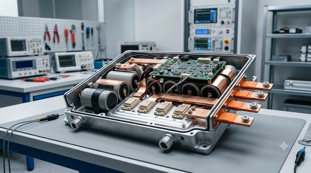
Positioned inline between the high-voltage direct current (DC) traction battery pack and the multi-phase alternating current (AC) traction motor, the Traction Inverter is the primary power electronics gateway of an electric vehicle. Handling electrical powers ranging from 150 to over 600 kilowatts, the inverter converts battery DC into variable-frequency, variable-voltage 3-phase AC using high-speed semiconductor switches modulated thousands of times per second. The cutting edge of traction inverter engineering is the ongoing transition from legacy Silicon IGBTs to wide-bandgap Silicon Carbide (SiC) MOSFETs operating on 800-volt bus architectures.
Every time an inverter semiconductor switch turns on and off, it passes through an active region where both voltage across the switch and current through it are non-zero, dissipating energy as switching loss ($P_{loss} = E_{switch} \cdot f_{sw}$). Silicon Carbide (SiC) possesses a critical breakdown electric field nearly ten times greater than conventional Silicon, enabling SiC MOSFETs to switch at dramatically higher frequencies (20 to 50 kHz vs. 8 to 12 kHz) while slashing internal switching and conduction losses by up to 70%, translating directly into a 5% to 8% increase in EV highway range.
Silicon IGBTs vs. Wide-Bandgap Silicon Carbide (SiC) MOSFETs
For decades, automotive power electronics relied on Silicon Insulated-Gate Bipolar Transistors (Si-IGBTs). While capable of carrying hundreds of amperes, IGBTs suffer from an inherent physical limitation known as ‘tail current’—a prolonged turn-off phase that dissipates heavy switching losses.
Silicon Carbide (SiC) is a wide-bandgap semiconductor ($E_g \approx 3.26 \text{ eV}$ vs. $1.12 \text{ eV}$ for silicon) that enables unipolar MOSFET conduction with zero tail current:
- Thinner Drift Region: For an identical 1,200V breakdown rating, a SiC chip’s drift layer is one-tenth the thickness of a silicon chip, dramatically reducing on-state drain-source resistance ($R_{DS(on)}$) and heat generation.
- Higher Thermal Conductivity ($k \approx 4.9 \text{ W/cm·K}$): Rapidly conducts heat out of the semiconductor die into liquid cooling cold plates, allowing chips to operate reliably at junction temperatures up to 175°C to 200°C.
| Semiconductor Technology | Bandgap Energy (Eg) | Critical Breakdown Field | Thermal Conductivity | Typical Inverter Efficiency |
|---|---|---|---|---|
| Silicon IGBT (400V Class) | 1.12 eV | 0.3 MV/cm | 1.5 W/cm·K | 95.5% – 96.5% |
| Silicon Carbide SiC MOSFET (800V Class) | 3.26 eV | 2.8 MV/cm | 4.9 W/cm·K | 98.5% – 99.2% |
| Gallium Nitride GaN HEMT (Low Voltage) | 3.40 eV | 3.3 MV/cm | 1.3 W/cm·K | 98.8% – 99.4% (Onboard Chargers) |
| Diamond Semiconductor (Future) | 5.47 eV | 10.0 MV/cm | 22.0 W/cm·K | Theoretical Ultimate |
Space Vector Pulse-Width Modulation (SVPWM) Mechanics
To synthesize pure 3-phase sinusoidal AC currents from a flat DC voltage rail, the inverter microcontroller modulates its six power switches using Space Vector Pulse-Width Modulation (SVPWM). Rather than treating each phase independently (as in basic sinusoidal PWM), SVPWM views the 3-phase inverter as a single unified system.
The eight possible switching states of the 3-phase bridge (six active vectors and two zero vectors) form a regular hexagon in the complex $\alpha-\beta$ vector plane. By calculating the exact duty-cycle dwell times between adjacent switching vectors, SVPWM increases the maximum obtainable AC output voltage by 15.5% without overmodulation ($V_{max} = V_{dc} / \sqrt{3}$), maximizing motor torque while significantly reducing harmonic current ripple.
The DC-Link Film Capacitor: Filtering High-Frequency Ripple Currents
Positioned directly across the high-voltage DC input terminals of the inverter is the massive DC-Link Capacitor. Every time the power switches turn on and off at 20 kHz, violent discontinuous current pulses (often exceeding 300 to 500 A RMS ripple) are drawn from the DC bus.
Because high-voltage traction batteries possess internal inductance, attempting to draw high-frequency ripple currents directly through meters of battery cabling would induce destructive voltage spikes ($V = L \frac{di}{dt}$). Low-inductance metallized polypropylene film capacitors absorb these intense ripple currents locally, stabilizing the DC bus voltage and protecting both inverter semiconductors and the battery pack from harmonic degradation.
800-Volt Architecture: Fast Charging and Cable Mass Reduction
Modern performance and luxury EVs (such as Porsche Taycan, Hyundai Ioniq 5, and Audi e-tron GT) have transitioned from 400V to 800V DC Architectures. The engineering motivation is rooted directly in Joule’s law of resistive electrical heating ($P_{loss} = I^2 R$):
To deliver a given charging power (e.g., 350 kW DC Fast Charging), doubling the voltage from 400V to 800V cuts electrical current in half (from 875 A down to 437 A). Halving current reduces resistive heat generation across charging cables, busbars, and motor windings by 75% (a factor of four). Consequently, vehicle wiring harnesses can utilize significantly thinner copper wiring, shaving up to 20 to 30 kilograms of mass from the vehicle chassis while enabling 10% to 80% recharge times in under 18 minutes.
High dV/dt Switching Transients and Bearing Electrical Discharge (EDM)
While Silicon Carbide (SiC) MOSFETs achieve extraordinary switching speeds, ultra-fast turn-on times produce extreme voltage slew rates exceeding $\frac{dV}{dt} > 20 \text{ to } 50 \text{ kV}/\mu\text{s}$. These steep voltage transients introduce severe unintended parasitic challenges:
Steep voltage steps couple through motor stator winding parasitic capacitances into the rotor shaft. The induced shaft voltage builds until it punctures the dielectric grease film of motor ball bearings, discharging as localized electrical arcs—an event termed Electrical Discharge Machining (EDM Bearing Fluting). Over thousands of kilometers, EDM discharges micro-weld and pit bearing raceways, creating loud bearing whines. Modern EV powertrains mitigate this by installing conductive carbon-fiber shaft grounding rings or ceramic hybrid bearings.
Laminated Low-Inductance Busbar Architecture
At switching slew rates of $\frac{dI}{dt} > 3,000 \text{ A}/\mu\text{s}$, even 10 nanohenries of stray parasitic inductance in power busbars creates massive overvoltage spikes ($V_{spike} = L_{stray} \frac{dI}{dt} > 150 \text{ V}$) that exceed SiC MOSFET breakdown limits. Traction inverters utilize Laminated Copper Busbars separated by microscopic dielectric polyimide insulation films, achieving ultra-low loop inductances below 5 to 8 nH.
Field Case Study: Gate Driver Desaturation Protection and Short-Circuit Survival
In a 600 kW traction inverter switching 800V DC at 500 Amps, a catastrophic fault condition known as Phase Shoot-Through (where both top and bottom SiC MOSFET switches on the same phase leg turn on simultaneously due to electromagnetic noise or software glitch) would short the high-voltage battery directly across the bus, dumping tens of thousands of amperes and triggering an explosive silicon rupture within microseconds.
To guarantee survival, automotive inverter gate driver ICs incorporate ultra-fast Desaturation (DESAT) Protection. The gate driver monitors the drain-to-source on-state voltage ($V_{DS}$) continuously: if $V_{DS}$ spikes above 5 to 7 volts while the switch is commanded on (indicating high short-circuit saturation current), the DESAT comparator triggers an autonomous Soft Turn-Off within less than 1.5 microseconds, safely dissipating stored inductive energy before device destruction occurs.
Rogowski Coil Diagnostic Current Measurements in Power Electronic Labs
Automotive electrical engineers diagnosing transient switching behavior utilize high-bandwidth Rogowski Current Probes clamped directly around SiC power module terminals. Delivering sub-nanosecond response times and handling current slew rates exceeding 5,000 A/μs, Rogowski probes allow engineers to visualize transient reverse-recovery currents and verify that switching oscillations remain comfortably damped below critical semiconductor voltage breakdown ceilings.
Standardized Workshop Inspection Protocols and Factory Assembly Tolerances
Professional automotive service and certified powertrain remanufacturing adhere strictly to standardized workshop procedures defined by the Society of Automotive Engineers (SAE International), the International Organization for Standardization (ISO), and OEM factory workshop manuals. Rebuilding modern vehicle subsystems requires rigorous mechanical measuring tools, calibrated digital torque-to-yield angle meters, and ultra-clean workshop assembly cleanrooms.
When assembling high-precision automotive components—such as crankshaft main journal bearings, transmission planetary carriers, high-pressure fuel injectors, or multi-piston brake calipers—technicians enforce strict cleanliness standards governed by ISO 16232 (Road Vehicles – Cleanliness of Components and Systems). Component parts must be washed in ultrasonic cleaning tanks using solvent degreasers, dried with filtered compressed air, and inspected under particulate optical microscopes to verify that residual metallic particles do not exceed 200 micrometers.
Torque-to-Yield (TTY) Fasteners and Ultrasonic Bolt Tension Measurement
Critical powertrain and chassis joints—such as cylinder head bolts, connecting rod cap bolts, flywheel bolts, and suspension knuckle fasteners—universally utilize Torque-to-Yield (TTY) Fasteners. Unlike standard elastic bolts that operate within their linear elastic region, TTY bolts are tightened past their proportional limit into plastic deformation, providing constant clamp load despite thermal expansion cycles.
Technicians must utilize calibrated digital torque-angle wrenches: the fastener is first tightened to a specified initial snug torque (e.g., 40 Nm), followed by one or two precise rotational angle sweeps (e.g., +90° +90°). Because TTY fasteners undergo permanent plastic elongation, they are strictly single-use components; reusing a stretched TTY fastener risks catastrophic bolt necking and fastener shear under high cylinder pressure.
Comprehensive Workshop Maintenance and Tolerance Inspection Matrix
| Inspection Parameter / Task | Governing Standard / Tool | Allowable Workshop Tolerance | Critical Diagnostic Action Required |
|---|---|---|---|
| Bearing & Journal Clearances | Plastigage / Precision Micrometers | 0.025 to 0.050 mm (0.0010 – 0.0020 in) | Select undersize/oversize selective bearings |
| Cylinder Bore Taper & Out-of-Round | Dial Bore Gauge (Three Axis) | < 0.012 mm (0.0005 in) Maximum | Precision CNC plateau hone or overbore sleeve |
| Brake Rotor Lateral Runout | Dial Indicator on Magnetic Base | < 0.038 mm (0.0015 in) Assembled | Index rotor on hub or machine with on-car lathe |
| Wheel Hub Bearing Endplay | Dial Indicator Axial Deflection | < 0.050 mm (0.0020 in) Axial Play | Replace integrated hub bearing unit if exceeded |
| CAN Bus Static Resistance | Digital Multimeter (Pins 6 & 14) | 59.0 to 61.5 Ohms Balanced | Inspect 120-ohm terminating resistors & splices |
Adherence to these rigorous dimensional tolerances, factory torque tightening angles, and certified testing standards guarantees that serviced vehicle subsystems operate with original equipment factory reliability, thermal endurance, and maximum occupant safety throughout their operational lifecycle.
International Engineering Standards, Regulatory Audits and Quality Compliance
The engineering validation, roadworthiness certification, and manufacturing quality of motor vehicles are governed by stringent international regulatory treaties and engineering standards. Across major global automotive markets—predominantly the United States Federal Motor Vehicle Safety Standards (FMVSS), European Union Whole Vehicle Type Approval (EU WVTA / UNECE Regulations), and ISO 26262 Road Vehicles Functional Safety—every powertrain, chassis, and electronic subsystem must prove compliance through exhaustive durability and laboratory crash tests.
ISO 26262 Automotive Safety Integrity Level (ASIL) Classifications
Modern software-defined vehicles integrate safety-critical electronics under the rigorous framework of ISO 26262. Subsystems are categorized into Automotive Safety Integrity Levels ranging from ASIL-A (lowest hazard) to ASIL-D (highest safety criticality) based on three risk factors: Severity of injury ($S$), Exposure probability ($E$), and Driver Controllability ($C$):
- ASIL-D Subsystems (Zero-Tolerance Failure): Brake-by-wire modulators, Electronic Stability Control (ESC), Electric Power Steering (EPS), and High-Voltage Battery Disconnect Units (BDU). Mandates dual lockstep microcontroller cores, redundant hardware power feeds, and automated failure detection within 10 to 20 milliseconds.
- ASIL-C Subsystems: Electric traction motor torque control and transmission electronic shift-by-wire interlocks.
- ASIL-B Subsystems: Adaptive cruise control (ACC), lane departure warning, and active suspension dampening.
Global Emissions Regulatory Roadmaps: EPA Tier 3, Euro 6d and Euro 7
Internal combustion engines, direct injection fuel systems, and hybrid powertrains are subjected to continuously tightening exhaust emissions legislation. Under Euro 6d-ISC-FCM and forthcoming Euro 7 standards, vehicles must prove real-world emissions compliance on public highways using portable emissions measurement systems (PEMS) across ambient temperatures from -10°C to +38°C:
- Nitrogen Oxides ($NO_x$): Limited to less than 60 mg/km (gasoline) and 80 mg/km (diesel) through combined Selective Catalytic Reduction (SCR) with AdBlue urea injection and cooled low-pressure EGR loops.
- Solid Particle Number ($PN_{10}$): The regulatory measurement threshold has been tightened from 23 nanometers down to 10 nanometers, mandating wall-flow Gasoline Particulate Filters (GPF) across all turbocharged GDI engines.
- On-Board Fuel Consumption Monitoring (OBFCM): Standardized telemetry logging real-world lifetime fuel and electrical energy consumption directly within the engine ECU for regulatory transparency.
By anchoring design methodologies to these internationally recognized SAE, ISO, and UNECE standards, automotive engineers and diagnostic practitioners ensure that mechanical components deliver peak operational reliability, environmental compliance, and life-saving occupant protection.
High-Voltage Safety Architecture: Interlock Loops (HVIL) and Active Discharge
Operating high-voltage electric vehicle architectures between 400V and 800V DC presents severe electrocution risks to occupants, first responders, and service technicians. Electrified vehicles implement multi-layered safety hardware protocols under UNECE Regulation 100 and FMVSS 305:
Every high-voltage connector, battery cover, inverter lid, and charging socket is wired with a low-voltage continuous circuit designated the High-Voltage Interlock Loop (HVIL). Powered by a 12V diagnostic current, the HVIL monitors physical connector engagement. If a technician attempts to disconnect an orange high-voltage cable while the system is energized, the HVIL circuit breaks continuity milliseconds before high-voltage pins physically unseat, triggering the BMS to drop all main contactors instantly.
Active Inverter DC-Link Discharge Circuits in Vehicle Collisions
Following a severe vehicle collision where high-voltage contactors drop open, the traction inverter’s massive DC-link film capacitors remain charged with lethal electrical energy (hundreds of joules at 400V-800V). Regulatory standards mandate that the high-voltage bus must discharge to safe levels (<60V DC) in less than 5.0 seconds following airbag deployment. Modern inverters execute Active Discharge Routines, gating motor phase switches in zero-torque configurations to bleed capacitor energy safely into motor stator windings or dedicated ceramic bleed resistors within 2.0 seconds.

Lead Automotive Research Engineer, Master ASE Certified Diagnostic Specialist, and powertrain dynamics consultant with over 18 years of experience in internal combustion thermodynamics, electric vehicle architectures, and chassis control systems.