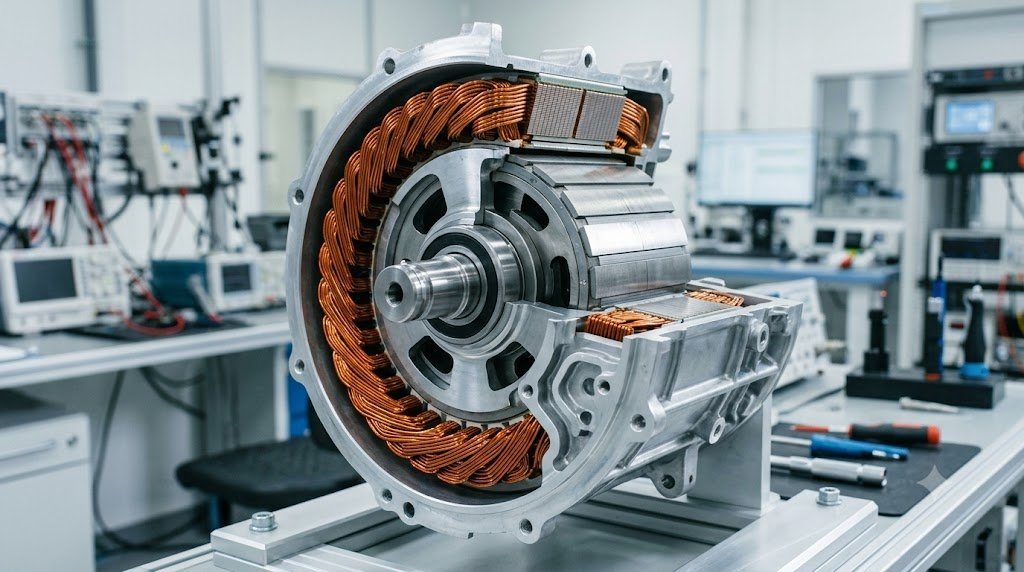
The traction motor is the electromechanical heart of an electric vehicle, responsible for converting high-voltage direct current (DC) supplied by the battery into rotational torque with instantaneous responsiveness and energy conversion efficiencies exceeding 94% to 97%. In modern production electric vehicles, two distinct alternating current (AC) motor architectures dominate the market: the Permanent Magnet Synchronous Motor (PMSM) and the AC Asynchronous Induction Motor (ACIM), operated via advanced Field-Oriented Control (FOC) algorithms.
All electric motors produce mechanical torque through the interaction between magnetic fields and current-carrying conductors governed by the Lorentz force: $\vec{F} = I (\vec{L} \times \vec{B})$. In an AC traction motor, a 3-phase sinusoidal stator winding generates a smoothly rotating magnetic stator field ($B_s$). Torque is produced as the rotor’s magnetic field ($B_r$) attempts to align with the rotating stator field: $\vec{T} = k (\vec{B}_s \times \vec{B}_r) = k B_s B_r \sin(\delta)$, where $\delta$ is the load angle.
Permanent Magnet Synchronous Motors: Interior Permanent Magnet (IPM) Geometry
The PMSM is the predominant traction choice for mainstream passenger electric vehicles prioritizing maximum energy density and compact packaging. The stator consists of copper windings housed within slotted silicon steel laminations. The rotor incorporates high-energy Neodymium-Iron-Boron ($Nd_2Fe_{14}B$) permanent magnets alloyed with dysprosium for thermal resistance.
Modern automotive PMSMs utilize Interior Permanent Magnet (IPM) rotors where V-shaped or delta-shaped magnet slabs are embedded deep within the rotor core rather than glued to the surface. This architecture delivers two distinct sources of mechanical torque:
- Magnetic Alignment Torque: Produced by the interaction between the stator magnetic flux and the permanent magnets.
- Reluctance Torque: Arises because the rotor exhibits magnetic asymmetry (the quadrature-axis inductance $L_q$ is higher than the direct-axis inductance $L_d$). The rotor naturally seeks the path of least magnetic resistance, providing an additional 20% to 30% of torque at high loads.
AC Induction Motors: The Robust, Rare-Earth-Free Alternative
Pioneered by Nikola Tesla and famously championed in early Tesla Model S and Model X powertrains, the AC Asynchronous Induction Motor (ACIM) utilizes a simple ‘squirrel-cage’ rotor comprising solid copper or aluminum conductor bars short-circuited at both ends by end-rings, with zero permanent magnets.
As the stator field rotates at synchronous speed ($\omega_s$), it cuts across the stationary rotor bars, inducing an electrical current via Faraday’s law of induction. This induced current creates the rotor magnetic field. Crucially, the rotor must always rotate at a speed slightly slower than the stator field—a difference termed Slip ($s = (\omega_s – \omega_r) / \omega_s$)—to maintain continuous flux cutting.
| Traction Motor Architecture | Rotor Field Source | Peak Energy Efficiency | Rare-Earth Dependency | Freewheeling Drag Loss |
|---|---|---|---|---|
| Interior Permanent Magnet (IPM-PMSM) | NdFeB Permanent Magnets | 96% – 97% (Wide Island) | High (Neodymium/Dysprosium) | High (Back-EMF Drag when Unpowered) |
| AC Asynchronous Induction (ACIM) | Induced Currents (Faraday) | 92% – 94% | Zero (Copper/Aluminum Only) | Zero (Magnetic Field Collapses when Unpowered) |
| Electrically Excited Synchronous (EESM) | Copper Windings via Slip Rings | 95% – 96% | Zero (BMW Gen5 eDrive) | Zero (Current Cut on Highway Cruise) |
| Switched Reluctance Motor (SRM) | Rotor Magnetic Saliency Only | 90% – 93% | Zero | Zero (Acoustic Noise Challenges) |
Field-Oriented Control (FOC): Direct-Quadrature (d-q) Transformation
To control high-power 3-phase AC traction motors with the directness and responsiveness of a DC motor, motor control inverters execute Field-Oriented Control (FOC). Using mathematical Clarke and Park transformations, 3-phase time-varying sinusoidal AC currents ($I_a, I_b, I_c$) are translated into a rotating 2-coordinate DC reference frame aligned with the rotor magnetic flux:
- Direct-Axis Current ($I_d$): Governs magnetic flux density aligned parallel with the rotor field.
- Quadrature-Axis Current ($I_q$): Governs electromagnetic torque production perpendicular to the rotor field.
By decoupling flux ($I_d$) from torque ($I_q$), the inverter microcontroller can command instantaneous torque steps in less than 1 millisecond simply by varying $I_q$, delivering immediate throttle response that internal combustion engines can never match.
Field Weakening: Breaking Past the Back-EMF Voltage Ceiling
As an IPM motor spins faster, spinning permanent magnets induce a rising counter-electromotive force (Back-EMF: $V_{bemf} \propto \omega$) across stator windings. Eventually, back-EMF matches the maximum DC bus voltage of the battery pack, preventing further current injection and capping top vehicle speed.
To break through this physical barrier, the inverter executes Field Weakening: it injects negative direct-axis current ($-I_d$) into the stator windings. This creates a magnetic counter-field that partially cancels the permanent magnet flux, suppressing back-EMF and allowing the motor to spin up to 18,000 to 20,000 RPM for high-speed highway cruising.
Maximum Torque Per Ampere (MTPA) Vector Trajectory Formulations
In Interior Permanent Magnet Synchronous Motors (IPM-PMSM), total electromagnetic torque combines both magnetic alignment torque and reluctance torque:
Te = (3/2) * p * [ Ψm * Iq + (Ld – Lq) * Id * Iq ]
Where $p$ is pole pairs, $\Psi_m$ is permanent magnet flux linkage, and $(L_d – L_q)$ represents rotor magnetic saliency. To minimize stator copper heating losses ($I^2 R$), the motor control inverter operates along the Maximum Torque Per Ampere (MTPA) Trajectory. Rather than injecting pure $I_q$ current, the controller introduces negative direct-axis current ($-I_d$), harvesting reluctance torque to maximize total motor output while minimizing battery current consumption.
Hairpin Stator Windings: Copper Fill Factor Optimization
Modern automotive traction stators have universally replaced traditional round stranded copper wire with Rectangular Hairpin Windings. Precision machines insert rigid rectangular copper pins into stator slots and laser-weld the hairpin tips together. Hairpin construction increases the copper slot fill factor from 45% up to 73% to 78%, drastically reducing stator resistance, improving slot thermal conduction into the cooling jacket, and boosting continuous power density by 30%.
Field Case Study: Rotor Resolver Sensor Misalignment and Inverter Overcurrent
Because Field-Oriented Control (FOC) requires knowledge of the exact angular position of the rotor magnetic flux to within fractions of a degree, electric traction motors incorporate a high-precision Variable Reluctance Resolver mounted on the rotor shaft tail.
The resolver consists of an excitation primary coil and two orthogonal secondary pickup coils (Sine and Cosine). If a mechanical shock, bearing runout, or loose resolver locking bolt shifts the resolver mounting angle by mere 2.0 degrees of mechanical rotation, the inverter’s Park transformation calculation becomes corrupted. The inverter injects torque-producing current ($I_q$) into the wrong electromagnetic vector axis, causing severe motor shudder, massive torque collapse, and catastrophic inverter overcurrent fault trips (DTC P0A3F Motor Resolver Position Circuit Malfunction).
Resolver Calibration and Angular Offset Adaptation Routines
Following traction motor or inverter replacement, technicians must perform an automated Resolver Offset Calibration. Utilizing dealership diagnostic software, the inverter injects known DC calibration test currents into stator windings to mechanically lock the rotor into a known magnetic detent position, measuring the raw resolver signal and writing the exact offset angle into permanent flash memory.
Standardized Workshop Inspection Protocols and Factory Assembly Tolerances
Professional automotive service and certified powertrain remanufacturing adhere strictly to standardized workshop procedures defined by the Society of Automotive Engineers (SAE International), the International Organization for Standardization (ISO), and OEM factory workshop manuals. Rebuilding modern vehicle subsystems requires rigorous mechanical measuring tools, calibrated digital torque-to-yield angle meters, and ultra-clean workshop assembly cleanrooms.
When assembling high-precision automotive components—such as crankshaft main journal bearings, transmission planetary carriers, high-pressure fuel injectors, or multi-piston brake calipers—technicians enforce strict cleanliness standards governed by ISO 16232 (Road Vehicles – Cleanliness of Components and Systems). Component parts must be washed in ultrasonic cleaning tanks using solvent degreasers, dried with filtered compressed air, and inspected under particulate optical microscopes to verify that residual metallic particles do not exceed 200 micrometers.
Torque-to-Yield (TTY) Fasteners and Ultrasonic Bolt Tension Measurement
Critical powertrain and chassis joints—such as cylinder head bolts, connecting rod cap bolts, flywheel bolts, and suspension knuckle fasteners—universally utilize Torque-to-Yield (TTY) Fasteners. Unlike standard elastic bolts that operate within their linear elastic region, TTY bolts are tightened past their proportional limit into plastic deformation, providing constant clamp load despite thermal expansion cycles.
Technicians must utilize calibrated digital torque-angle wrenches: the fastener is first tightened to a specified initial snug torque (e.g., 40 Nm), followed by one or two precise rotational angle sweeps (e.g., +90° +90°). Because TTY fasteners undergo permanent plastic elongation, they are strictly single-use components; reusing a stretched TTY fastener risks catastrophic bolt necking and fastener shear under high cylinder pressure.
Comprehensive Workshop Maintenance and Tolerance Inspection Matrix
| Inspection Parameter / Task | Governing Standard / Tool | Allowable Workshop Tolerance | Critical Diagnostic Action Required |
|---|---|---|---|
| Bearing & Journal Clearances | Plastigage / Precision Micrometers | 0.025 to 0.050 mm (0.0010 – 0.0020 in) | Select undersize/oversize selective bearings |
| Cylinder Bore Taper & Out-of-Round | Dial Bore Gauge (Three Axis) | < 0.012 mm (0.0005 in) Maximum | Precision CNC plateau hone or overbore sleeve |
| Brake Rotor Lateral Runout | Dial Indicator on Magnetic Base | < 0.038 mm (0.0015 in) Assembled | Index rotor on hub or machine with on-car lathe |
| Wheel Hub Bearing Endplay | Dial Indicator Axial Deflection | < 0.050 mm (0.0020 in) Axial Play | Replace integrated hub bearing unit if exceeded |
| CAN Bus Static Resistance | Digital Multimeter (Pins 6 & 14) | 59.0 to 61.5 Ohms Balanced | Inspect 120-ohm terminating resistors & splices |
Adherence to these rigorous dimensional tolerances, factory torque tightening angles, and certified testing standards guarantees that serviced vehicle subsystems operate with original equipment factory reliability, thermal endurance, and maximum occupant safety throughout their operational lifecycle.
International Engineering Standards, Regulatory Audits and Quality Compliance
The engineering validation, roadworthiness certification, and manufacturing quality of motor vehicles are governed by stringent international regulatory treaties and engineering standards. Across major global automotive markets—predominantly the United States Federal Motor Vehicle Safety Standards (FMVSS), European Union Whole Vehicle Type Approval (EU WVTA / UNECE Regulations), and ISO 26262 Road Vehicles Functional Safety—every powertrain, chassis, and electronic subsystem must prove compliance through exhaustive durability and laboratory crash tests.
ISO 26262 Automotive Safety Integrity Level (ASIL) Classifications
Modern software-defined vehicles integrate safety-critical electronics under the rigorous framework of ISO 26262. Subsystems are categorized into Automotive Safety Integrity Levels ranging from ASIL-A (lowest hazard) to ASIL-D (highest safety criticality) based on three risk factors: Severity of injury ($S$), Exposure probability ($E$), and Driver Controllability ($C$):
- ASIL-D Subsystems (Zero-Tolerance Failure): Brake-by-wire modulators, Electronic Stability Control (ESC), Electric Power Steering (EPS), and High-Voltage Battery Disconnect Units (BDU). Mandates dual lockstep microcontroller cores, redundant hardware power feeds, and automated failure detection within 10 to 20 milliseconds.
- ASIL-C Subsystems: Electric traction motor torque control and transmission electronic shift-by-wire interlocks.
- ASIL-B Subsystems: Adaptive cruise control (ACC), lane departure warning, and active suspension dampening.
Global Emissions Regulatory Roadmaps: EPA Tier 3, Euro 6d and Euro 7
Internal combustion engines, direct injection fuel systems, and hybrid powertrains are subjected to continuously tightening exhaust emissions legislation. Under Euro 6d-ISC-FCM and forthcoming Euro 7 standards, vehicles must prove real-world emissions compliance on public highways using portable emissions measurement systems (PEMS) across ambient temperatures from -10°C to +38°C:
- Nitrogen Oxides ($NO_x$): Limited to less than 60 mg/km (gasoline) and 80 mg/km (diesel) through combined Selective Catalytic Reduction (SCR) with AdBlue urea injection and cooled low-pressure EGR loops.
- Solid Particle Number ($PN_{10}$): The regulatory measurement threshold has been tightened from 23 nanometers down to 10 nanometers, mandating wall-flow Gasoline Particulate Filters (GPF) across all turbocharged GDI engines.
- On-Board Fuel Consumption Monitoring (OBFCM): Standardized telemetry logging real-world lifetime fuel and electrical energy consumption directly within the engine ECU for regulatory transparency.
By anchoring design methodologies to these internationally recognized SAE, ISO, and UNECE standards, automotive engineers and diagnostic practitioners ensure that mechanical components deliver peak operational reliability, environmental compliance, and life-saving occupant protection.
High-Voltage Safety Architecture: Interlock Loops (HVIL) and Active Discharge
Operating high-voltage electric vehicle architectures between 400V and 800V DC presents severe electrocution risks to occupants, first responders, and service technicians. Electrified vehicles implement multi-layered safety hardware protocols under UNECE Regulation 100 and FMVSS 305:
Every high-voltage connector, battery cover, inverter lid, and charging socket is wired with a low-voltage continuous circuit designated the High-Voltage Interlock Loop (HVIL). Powered by a 12V diagnostic current, the HVIL monitors physical connector engagement. If a technician attempts to disconnect an orange high-voltage cable while the system is energized, the HVIL circuit breaks continuity milliseconds before high-voltage pins physically unseat, triggering the BMS to drop all main contactors instantly.
Active Inverter DC-Link Discharge Circuits in Vehicle Collisions
Following a severe vehicle collision where high-voltage contactors drop open, the traction inverter’s massive DC-link film capacitors remain charged with lethal electrical energy (hundreds of joules at 400V-800V). Regulatory standards mandate that the high-voltage bus must discharge to safe levels (<60V DC) in less than 5.0 seconds following airbag deployment. Modern inverters execute Active Discharge Routines, gating motor phase switches in zero-torque configurations to bleed capacitor energy safely into motor stator windings or dedicated ceramic bleed resistors within 2.0 seconds.

Lead Automotive Research Engineer, Master ASE Certified Diagnostic Specialist, and powertrain dynamics consultant with over 18 years of experience in internal combustion thermodynamics, electric vehicle architectures, and chassis control systems.