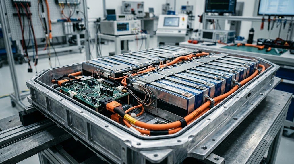
The high-voltage traction battery pack constitutes the electrochemical epicenter and highest-cost subsystem of every modern Battery Electric Vehicle (BEV). Storing between 50 and 120 kilowatt-hours (kWh) of electrical energy at potentials between 400V and 800V DC, automotive battery packs comprise thousands of individual lithium-ion cells connected in series and parallel. Operating this massive electrochemical substation safely and durably requires an advanced Battery Management System (BMS) to monitor cell voltages, compute state metrics, execute cell balancing, and guard against catastrophic thermal runaway.
A commercial lithium-ion cell (such as Nickel-Manganese-Cobalt, NMC 811) operates within a strict electrochemical potential window between 2.8V (fully discharged) and 4.2V (fully charged). Overcharging a cell past 4.25V causes lithium metal to plate out as dendrites onto the graphite anode and forces the cathode to release volatile oxygen gas, initiating thermal runaway. Over-discharging beneath 2.5V dissolves copper current collectors into the electrolyte, creating internal short circuits upon subsequent recharge. The BMS enforces these physical safety boundaries down to the millivolt.
BMS System Architecture: Master-Slave Distributed Topology
Modern automotive battery packs utilize a distributed Master-Slave BMS Topology. The battery pack is partitioned into physical modules, each monitored by a dedicated Cell Monitoring Unit (CMU / Slave Board):
- Slave Monitoring Units (CMUs): High-precision multi-channel Analog Front End (AFE) integrated circuits measure the voltage of every individual series-connected cell to within ±1 millivolt and monitor temperatures via NTC thermistors placed between adjacent cells. Data is transmitted via isolated daisy-chain SPI or wireless mesh networks (wBMS) to the master controller.
- Master Battery Controller (BMU): Computes core state estimations, commands high-voltage pyrotechnic safety fuses and contactors, monitors pack insulation resistance relative to chassis ground, and interfaces with the vehicle’s central gateway via CAN-FD.
State Estimation: State of Charge (SoC) and State of Health (SoH)
Unlike a petroleum fuel tank where fuel volume can be measured with a simple mechanical float, the remaining energy in a battery cannot be measured directly. The BMS must mathematically infer two critical state variables:
- State of Charge (SoC): The percentage of usable charge remaining. Computed by combining Coulomb Counting (integrating current over time: $SoC(t) = SoC_0 – \frac{1}{Q_n} \int I dt$) with Extended Kalman Filtering (EKF) that correlates open-circuit voltage (OCV) curves while filtering out measurement noise and internal resistance voltage drops ($V = OCV – I R_{int}$).
- State of Health (SoH): A metric of irreversible cell aging, quantified by lost total capacity ($Q_{max} / Q_{nominal}$) and internal impedance growth ($\Delta R_{int}$). When SoH degrades beneath 70% to 80%, the battery pack is deemed retired from automotive service and transitioned to secondary stationary grid storage.
| Traction Cell Chemistry | Nominal Cell Voltage | Gravimetric Energy Density | Thermal Runaway Trigger Temp | Cycle Life Expectancy |
|---|---|---|---|---|
| Lithium Iron Phosphate (LFP) | 3.2 V | 140 – 170 Wh/kg | 270°C (Extremely Stable) | 3,000 – 5,000 Cycles |
| NMC 622 (Nickel-Manganese-Cobalt) | 3.6 – 3.7 V | 220 – 250 Wh/kg | 210°C | 1,500 – 2,000 Cycles |
| NMC 811 (High Nickel) | 3.7 V | 260 – 300 Wh/kg | 180°C – 190°C | 1,000 – 1,500 Cycles |
| Lithium Titanate (LTO) | 2.4 V | 80 – 110 Wh/kg | 300°C+ (Zero Dendrites) | 15,000 – 20,000 Cycles |
Cell Balancing Physics: Passive Bleeding vs. Active Charge Transfer
Due to microscopic manufacturing tolerances and uneven temperature gradients across the pack, series-connected cells do not charge or discharge at identical rates. If left uncorrected, the cell with the lowest capacity hits 4.2V first during charging (shutting down pack charging prematurely) and drops to 2.8V first during driving (limiting driving range). To maintain uniform state across the string, the BMS executes Cell Balancing:
- Passive Balancing: Shunts small bleeding currents (50 to 200 mA) through switched balance resistors across overcharged cells during the top of the charge cycle, dissipating excess energy as modest heat until all cell voltages match. Passive balancing is simple, low-cost, and reliable.
- Active Balancing: Utilizes switched-capacitor or bidirectional inductive DC-DC converters to physically transfer energy from high-voltage cells to low-voltage cells without thermal dissipation losses. While highly efficient, active balancing adds substantial circuitry complexity and cost.
Thermal Runaway Mechanics and Pyrofuse Isolation
Thermal Runaway is the primary catastrophic failure mode of high-energy lithium-ion batteries. If an internal defect or external mechanical penetration compromises the porous polymer separator, a localized microscopic short circuit occurs. Exothermic chemical reactions cascade:
At 80°C-120°C, the protective Solid Electrolyte Interphase (SEI) layer decomposes. At 130°C, the separator melts, triggering widespread internal short circuits. Above 180°C-210°C, cathode metal oxides decompose, releasing pressurized oxygen gas that aggressively oxidizes the flammable organic liquid carbonate solvent in a self-sustaining exothermic blaze that can exceed 1,000°C within seconds.
To safeguard passengers, modern battery enclosures incorporate Aerogel and Mica Thermal Barrier Sheets between cells to prevent cell-to-cell thermal propagation. Electrically, the master BMS can fire a high-speed pyrotechnic safety disconnect (Pyrofuse) in less than 2 milliseconds, physically severing the high-voltage busbar before external short-circuit currents can ignite the pack.
Equivalent Circuit Modeling (Thevenin Model) and Kalman Filter State Estimation
Because direct measurement of internal chemical state is impossible in automotive traction packs, advanced BMS algorithms model lithium-ion cells using a First-Order Thevenin Equivalent Circuit Model:
Vterminal(t) = OCV(SoC) – I(t) * R0 – VRC(t)
Where $R_0$ is high-frequency ohmic resistance, and the parallel $R_1-C_1$ pair models transient electrochemical charge transfer and mass diffusion polarization over time. By executing an Extended Kalman Filter (EKF), the BMS recursively updates state vectors, achieving State-of-Charge (SoC) estimation accuracy to within ±1.5% across dynamic driving cycles and extreme temperatures.
High-Voltage Isolation Resistance Monitoring (Megohmmeter Telemetry)
Under international safety standards (ECE R100), the high-voltage DC bus (400V/800V) must remain completely isolated from vehicle 12V chassis ground. The BMS incorporates active Isolation Monitoring Circuitry that injects low-frequency AC test signals to verify isolation resistance continuously. Regulations mandate a minimum electrical isolation of 500 Ohms per Volt ($> 200 \text{ k}\Omega$ for 400V systems, $> 400 \text{ k}\Omega$ for 800V systems); any isolation drop triggers immediate high-voltage contactor shutdown.
Field Case Study: Dendrite Micro-Shorting and High Self-Discharge Rates
In high-mileage EV battery packs or packs subjected to frequent freezing-temperature DC fast charging, lithium metal can deposit onto the graphite anode surface rather than intercalating cleanly—a degradation mechanism termed Lithium Plating. Over time, metallic lithium grows as microscopic tree-like needles called Dendrites.
Eventually, a dendrite pierces the porous polymer separator, creating a microscopic soft short circuit between cathode and anode. The compromised cell does not instantly enter thermal runaway; instead, it exhibits a massive spike in Self-Discharge Rate. While the vehicle is parked overnight, the faulted cell drains voltage down to 3.2V while neighboring cells remain at 4.0V. Advanced BMS firmware detects this anomalous delta voltage ($V_{delta} > 80 \text{ mV}$) during sleep mode, flagging pre-catastrophic warning DTCs and preventing charging before full thermal runaway occurs.
High-Voltage Contactor Pre-Charge Resistor Welded Contact Detection
When an EV is keyed on, connecting a 400V battery directly to the inverter’s massive DC-link capacitor bank would draw an instantaneous inrush current exceeding thousands of amperes, instantly welding high-voltage contactor points solid. To prevent this, the BMS first closes a small Pre-Charge Contactor routed through a heavy-duty ceramic power resistor (typically 30 to 50 ohms).
Once inverter bus voltage reaches 95% of battery voltage, the main positive contactor closes and the pre-charge contactor opens. The BMS executes automated contactor integrity checks upon every shutdown: if voltage across open contactor terminals fails to collapse, the BMS detects a welded contactor, locks out high-voltage startup, and illuminates warning indicators.
Standardized Workshop Inspection Protocols and Factory Assembly Tolerances
Professional automotive service and certified powertrain remanufacturing adhere strictly to standardized workshop procedures defined by the Society of Automotive Engineers (SAE International), the International Organization for Standardization (ISO), and OEM factory workshop manuals. Rebuilding modern vehicle subsystems requires rigorous mechanical measuring tools, calibrated digital torque-to-yield angle meters, and ultra-clean workshop assembly cleanrooms.
When assembling high-precision automotive components—such as crankshaft main journal bearings, transmission planetary carriers, high-pressure fuel injectors, or multi-piston brake calipers—technicians enforce strict cleanliness standards governed by ISO 16232 (Road Vehicles – Cleanliness of Components and Systems). Component parts must be washed in ultrasonic cleaning tanks using solvent degreasers, dried with filtered compressed air, and inspected under particulate optical microscopes to verify that residual metallic particles do not exceed 200 micrometers.
Torque-to-Yield (TTY) Fasteners and Ultrasonic Bolt Tension Measurement
Critical powertrain and chassis joints—such as cylinder head bolts, connecting rod cap bolts, flywheel bolts, and suspension knuckle fasteners—universally utilize Torque-to-Yield (TTY) Fasteners. Unlike standard elastic bolts that operate within their linear elastic region, TTY bolts are tightened past their proportional limit into plastic deformation, providing constant clamp load despite thermal expansion cycles.
Technicians must utilize calibrated digital torque-angle wrenches: the fastener is first tightened to a specified initial snug torque (e.g., 40 Nm), followed by one or two precise rotational angle sweeps (e.g., +90° +90°). Because TTY fasteners undergo permanent plastic elongation, they are strictly single-use components; reusing a stretched TTY fastener risks catastrophic bolt necking and fastener shear under high cylinder pressure.
Comprehensive Workshop Maintenance and Tolerance Inspection Matrix
| Inspection Parameter / Task | Governing Standard / Tool | Allowable Workshop Tolerance | Critical Diagnostic Action Required |
|---|---|---|---|
| Bearing & Journal Clearances | Plastigage / Precision Micrometers | 0.025 to 0.050 mm (0.0010 – 0.0020 in) | Select undersize/oversize selective bearings |
| Cylinder Bore Taper & Out-of-Round | Dial Bore Gauge (Three Axis) | < 0.012 mm (0.0005 in) Maximum | Precision CNC plateau hone or overbore sleeve |
| Brake Rotor Lateral Runout | Dial Indicator on Magnetic Base | < 0.038 mm (0.0015 in) Assembled | Index rotor on hub or machine with on-car lathe |
| Wheel Hub Bearing Endplay | Dial Indicator Axial Deflection | < 0.050 mm (0.0020 in) Axial Play | Replace integrated hub bearing unit if exceeded |
| CAN Bus Static Resistance | Digital Multimeter (Pins 6 & 14) | 59.0 to 61.5 Ohms Balanced | Inspect 120-ohm terminating resistors & splices |
Adherence to these rigorous dimensional tolerances, factory torque tightening angles, and certified testing standards guarantees that serviced vehicle subsystems operate with original equipment factory reliability, thermal endurance, and maximum occupant safety throughout their operational lifecycle.
International Engineering Standards, Regulatory Audits and Quality Compliance
The engineering validation, roadworthiness certification, and manufacturing quality of motor vehicles are governed by stringent international regulatory treaties and engineering standards. Across major global automotive markets—predominantly the United States Federal Motor Vehicle Safety Standards (FMVSS), European Union Whole Vehicle Type Approval (EU WVTA / UNECE Regulations), and ISO 26262 Road Vehicles Functional Safety—every powertrain, chassis, and electronic subsystem must prove compliance through exhaustive durability and laboratory crash tests.
ISO 26262 Automotive Safety Integrity Level (ASIL) Classifications
Modern software-defined vehicles integrate safety-critical electronics under the rigorous framework of ISO 26262. Subsystems are categorized into Automotive Safety Integrity Levels ranging from ASIL-A (lowest hazard) to ASIL-D (highest safety criticality) based on three risk factors: Severity of injury ($S$), Exposure probability ($E$), and Driver Controllability ($C$):
- ASIL-D Subsystems (Zero-Tolerance Failure): Brake-by-wire modulators, Electronic Stability Control (ESC), Electric Power Steering (EPS), and High-Voltage Battery Disconnect Units (BDU). Mandates dual lockstep microcontroller cores, redundant hardware power feeds, and automated failure detection within 10 to 20 milliseconds.
- ASIL-C Subsystems: Electric traction motor torque control and transmission electronic shift-by-wire interlocks.
- ASIL-B Subsystems: Adaptive cruise control (ACC), lane departure warning, and active suspension dampening.
Global Emissions Regulatory Roadmaps: EPA Tier 3, Euro 6d and Euro 7
Internal combustion engines, direct injection fuel systems, and hybrid powertrains are subjected to continuously tightening exhaust emissions legislation. Under Euro 6d-ISC-FCM and forthcoming Euro 7 standards, vehicles must prove real-world emissions compliance on public highways using portable emissions measurement systems (PEMS) across ambient temperatures from -10°C to +38°C:
- Nitrogen Oxides ($NO_x$): Limited to less than 60 mg/km (gasoline) and 80 mg/km (diesel) through combined Selective Catalytic Reduction (SCR) with AdBlue urea injection and cooled low-pressure EGR loops.
- Solid Particle Number ($PN_{10}$): The regulatory measurement threshold has been tightened from 23 nanometers down to 10 nanometers, mandating wall-flow Gasoline Particulate Filters (GPF) across all turbocharged GDI engines.
- On-Board Fuel Consumption Monitoring (OBFCM): Standardized telemetry logging real-world lifetime fuel and electrical energy consumption directly within the engine ECU for regulatory transparency.
By anchoring design methodologies to these internationally recognized SAE, ISO, and UNECE standards, automotive engineers and diagnostic practitioners ensure that mechanical components deliver peak operational reliability, environmental compliance, and life-saving occupant protection.
High-Voltage Safety Architecture: Interlock Loops (HVIL) and Active Discharge
Operating high-voltage electric vehicle architectures between 400V and 800V DC presents severe electrocution risks to occupants, first responders, and service technicians. Electrified vehicles implement multi-layered safety hardware protocols under UNECE Regulation 100 and FMVSS 305:
Every high-voltage connector, battery cover, inverter lid, and charging socket is wired with a low-voltage continuous circuit designated the High-Voltage Interlock Loop (HVIL). Powered by a 12V diagnostic current, the HVIL monitors physical connector engagement. If a technician attempts to disconnect an orange high-voltage cable while the system is energized, the HVIL circuit breaks continuity milliseconds before high-voltage pins physically unseat, triggering the BMS to drop all main contactors instantly.
Active Inverter DC-Link Discharge Circuits in Vehicle Collisions
Following a severe vehicle collision where high-voltage contactors drop open, the traction inverter’s massive DC-link film capacitors remain charged with lethal electrical energy (hundreds of joules at 400V-800V). Regulatory standards mandate that the high-voltage bus must discharge to safe levels (<60V DC) in less than 5.0 seconds following airbag deployment. Modern inverters execute Active Discharge Routines, gating motor phase switches in zero-torque configurations to bleed capacitor energy safely into motor stator windings or dedicated ceramic bleed resistors within 2.0 seconds.

Lead Automotive Research Engineer, Master ASE Certified Diagnostic Specialist, and powertrain dynamics consultant with over 18 years of experience in internal combustion thermodynamics, electric vehicle architectures, and chassis control systems.