In the physical science of automotive propulsion, reciprocating internal combustion engines represent classical thermal machines designed to transform chemical enthalpy locked within hydrocarbon fuel molecules into usable mechanical shaft torque. Over a century of thermal engineering has refined the four-stroke reciprocating architecture—comprising intake, compression, power, and exhaust strokes—into specialized thermodynamic cycles tailored for distinct operational envelopes: the constant-volume Otto cycle, the constant-pressure Diesel cycle, the over-expanded Atkinson cycle, and the variable valve-timed Miller cycle.
The foundational efficiency of any reciprocating air-standard heat engine is dictated by its compression ratio ($r = V_1 / V_2$) and the specific heat ratio of the working fluid ($\gamma = C_p / C_v \approx 1.40$ for ambient air). According to classical thermodynamic derivation, the ideal Otto thermal efficiency follows: $\eta_{th} = 1 – (1 / r^{\gamma – 1})$. Raising the geometric compression ratio increases thermal efficiency, but introduces severe knock limits dictated by the autoignition temperature of the fuel-air charge.
The Ideal Air-Standard Otto Cycle: Isochoric Combustion Mechanics
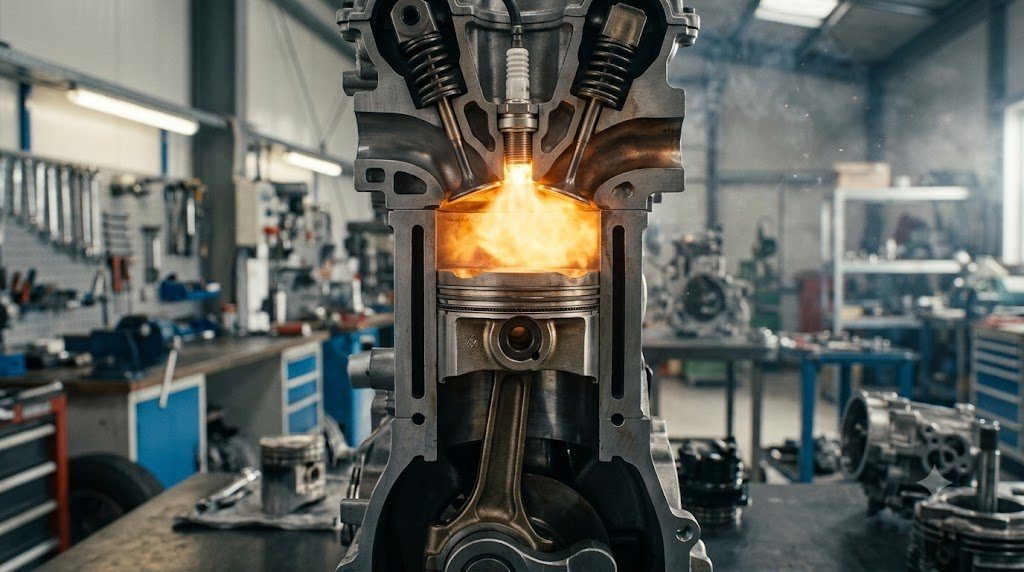
The idealized Otto cycle serves as the theoretical benchmark for spark-ignition (SI) gasoline engines. Operating through four distinct non-flow thermodynamic processes within the enclosed cylinder boundary, the cycle models instantaneous combustion as a purely constant-volume (isochoric) heat addition:
- Process 1-2 (Isentropic Compression): The piston moves from Bottom Dead Center (BDC) to Top Dead Center (TDC), compressing the homogeneous fuel-air mixture reversibly and adiabatically according to $P_1 V_1^\gamma = P_2 V_2^\gamma$.
- Process 2-3 (Constant-Volume Heat Addition): The spark plug ignites the pre-mixed charge at TDC. In the theoretical model, combustion occurs instantaneously while the piston dwells momentarily at TDC ($V_2 = V_3$), driving peak cylinder pressure ($P_3$) to 60-120 bar and temperature ($T_3$) to 2,200-2,600 K.
- Process 3-4 (Isentropic Expansion / Power): High-pressure gas forces the piston downward from TDC to BDC, performing thermodynamic boundary work ($W = \int P dV$) on the reciprocating piston face.
- Process 4-1 (Constant-Volume Heat Rejection): The exhaust valve opens, releasing residual thermal energy to the ambient atmosphere at constant cylinder volume ($V_4 = V_1$).
The Diesel Cycle: Constant-Pressure Heat Addition and High Compression
Conceived by Rudolf Diesel to eliminate the pre-ignition knock limit inherent in pre-mixed gasoline engines, the compression-ignition (CI) Diesel cycle compresses pure ambient air to extreme volumetric ratios ($r = 16.0:1$ to $22.0:1$). The resulting compression stroke heats the in-cylinder air well above 800 K (527°C), which exceeds the spontaneous autoignition temperature of atomized diesel fuel.
Fuel is introduced directly into the combustion chamber via high-pressure common-rail injectors operating at pressures between 1,800 and 2,500 bar. Combustion occurs progressively as fuel is sprayed, modeling a constant-pressure (isobaric) heat addition process ($P_2 = P_3$) characterized by the Cut-Off Ratio ($r_c = V_3 / V_2$). The theoretical thermal efficiency of the Diesel cycle is formulated as:
ηDiesel = 1 – (1 / rγ-1) * [(rcγ – 1) / (γ * (rc – 1))]
Because the term $[(r_c^\gamma – 1) / (\gamma(r_c – 1))]$ is always greater than unity for any non-zero fuel injection duration, an Otto cycle operating at the same compression ratio would yield higher thermal efficiency. However, because diesel engines operate without knock limits, their much higher compression ratios ($r \approx 18:1$ vs. $r \approx 10.5:1$ in gasoline engines) result in substantially higher practical thermal efficiencies in production vehicles (42-46% vs. 30-36%).
| Thermodynamic Combustion Cycle | Typical Compression Ratio | Heat Addition Mechanism | Peak Thermal Efficiency | Primary Production Application |
|---|---|---|---|---|
| Standard Otto Cycle | 9.5:1 to 11.5:1 | Constant Volume (Isochoric) | 30% – 36% | Mainstream Gasoline Passenger Cars |
| Direct Injection Diesel | 15.5:1 to 21.0:1 | Constant Pressure (Isobaric) | 40% – 46% | Heavy Transport & Commercial Turbodiesels |
| Atkinson Cycle | 12.0:1 to 14.0:1 (Expansion) | Extended Isentropic Expansion | 38% – 41% | Naturally Aspirated Hybrid Electric Vehicles |
| Miller Cycle (Supercharged) | 8.5:1 (Comp) / 11.5:1 (Exp) | Early/Late Intake Valve Closure | 36% – 42% | Downsized Turbocharged Gasoline Engines |
The Atkinson and Miller Cycles: Extended Expansion for Hybrid Efficiency
In a standard Otto cycle, when the exhaust valve opens at Process 4, significant high-pressure thermal enthalpy (typically 3 to 5 bar residual pressure) is dumped wastefully into the exhaust manifold as blowdown loss. In 1882, James Atkinson patented a mechanical linkage that produced an expansion stroke longer than the compression stroke, extracting additional thermodynamic work from the expanding burning gas.
In modern automotive engineering, the Atkinson Cycle is implemented electronically without complex mechanical linkages by utilizing Late Intake Valve Closing (LIVC) via variable valve timing (VVT). The intake valve remains unseated during the initial 20% to 30% of the upward compression stroke, pushing a portion of the trapped intake charge back into the intake manifold. Consequently, the effective compression ratio ($r_{comp} \approx 8.5:1$) remains safely below the detonation limit, while the full geometric expansion ratio ($r_{exp} \approx 13.0:1$ to $14.0:1$) extracts maximum kinetic energy from the burning charge.
The Miller Cycle applies this over-expanded thermodynamic concept to forced induction engines. By combining late (or extremely early) intake valve closure with positive manifold boost pressure delivered by a roots supercharger or twin-scroll turbocharger, the Miller cycle achieves high volumetric efficiency without elevated compression temperatures that induce spark knock.
P-V and T-S Diagram Analysis: Work Output and Pumping Losses
The net indicated work ($W_{net}$) produced per engine cycle is represented graphically by the enclosed area of the Pressure-Volume ($P-V$) diagram. In naturally aspirated engines, the lower pumping loop—governed by throttling depression across the intake butterfly valve—represents negative work deducted from gross indicated power:
Wnet = Wgross – Wpump = ∮ P dV
At light vehicle cruising loads, throttle throttling plates create manifold vacuum levels exceeding -0.6 to -0.8 bar relative to atmosphere, forcing the piston to pull against vacuum during the intake stroke. Atkinson and Miller cycles eliminate these severe throttling losses by operating with nearly wide-open throttle plates at partial load, controlling cylinder air charge volume purely through intake valve closure timing.
Mean Effective Pressure (BMEP & IMEP) and Volumetric Efficiency Derivations
In the comparative thermodynamic evaluation of reciprocating internal combustion engines, raw torque and power figures are insufficient because they scale directly with displacement volume. Powertrain development engineers evaluate cycle performance using Brake Mean Effective Pressure (BMEP)—a normalized parameter representing theoretical constant cylinder pressure that would produce the equivalent measured shaft brake torque ($T_b$) per power stroke:
BMEP = (4 * π * Tb) / Vd [Four-Stroke Engines]
Where $V_d$ is the total engine displacement volume ($m^3$) and $T_b$ is delivered torque ($Nm$). In naturally aspirated Otto engines, peak BMEP is physically constrained between 10.5 and 13.0 bar (150 to 190 psi) by ambient atmospheric pressure and intake valve throttling losses. In modern high-boost Miller-cycle turbocharged engines, BMEP reaches 24.0 to 30.0 bar (350 to 435 psi), while heavy commercial turbodiesel engines exceed 32.0 bar.
In-Cylinder Pressure Transducer Analysis: Polytropic Exponent Tracking
During dynamometer combustion development, laboratory piezoelectric pressure transducers flush-mounted in the cylinder combustion roof sample in-cylinder pressure at 0.1-degree crank angle increments. By plotting $\ln(P)$ versus $\ln(V)$, calibrators extract the real-world Polytropic Exponent ($n$) during compression ($P V^n = C$). While ideal air assumes isentropic $\gamma = 1.40$, heat rejection into cylinder wall cooling jackets and blow-by past piston rings lowers compression polytropic exponents to $n \approx 1.30$ to $1.34$, providing empirical insight into combustion chamber heat transfer efficiency.
Field Case Study: Low-Speed Pre-Ignition (LSPI) Catastrophic Piston Destruction
In modern downsized, high-boost direct-injection gasoline engines operating at high engine load and low RPM (e.g., 1,500 to 2,200 RPM in 6th gear climbing a highway grade), powertrain engineers uncovered an unprecedented combustion failure mode: Low-Speed Pre-Ignition (LSPI). Unlike traditional high-RPM knock (which occurs after the spark plug fires), LSPI is an uncontrolled spontaneous pre-ignition event that occurs before the spark plug fires during the compression stroke.
Laboratory combustion camera investigations revealed the root cause: droplets of engine oil-fuel emulsion washed off cylinder liners or glowing carbon flakes ignite the compressed charge prematurely. Peak in-cylinder combustion pressures spike catastrophically to exceeding 180 to 250 bar (2,600 to 3,600 psi)—over three times design limits. The violent shockwave instantly fractures cast aluminum piston ring lands and buckles forged connecting rods.
Tribological Mitigation via API SP / ILSAC GF-6 Engine Oil Formulations
Automotive lubricant manufacturers and OEMs responded by re-engineering motor oil chemistry. Chemical research demonstrated that traditional calcium-based detergent additives violently promote LSPI droplet autoignition. Under the modern API SP and ILSAC GF-6 standards, calcium concentrations are cut significantly and replaced with magnesium-based detergent additives and zinc dialkyldithiophosphate (ZDDP) inhibitors, reducing LSPI event frequencies by over 95% in modern production turbocharged engines.
Standardized Workshop Inspection Protocols and Factory Assembly Tolerances
Professional automotive service and certified powertrain remanufacturing adhere strictly to standardized workshop procedures defined by the Society of Automotive Engineers (SAE International), the International Organization for Standardization (ISO), and OEM factory workshop manuals. Rebuilding modern vehicle subsystems requires rigorous mechanical measuring tools, calibrated digital torque-to-yield angle meters, and ultra-clean workshop assembly cleanrooms.
When assembling high-precision automotive components—such as crankshaft main journal bearings, transmission planetary carriers, high-pressure fuel injectors, or multi-piston brake calipers—technicians enforce strict cleanliness standards governed by ISO 16232 (Road Vehicles – Cleanliness of Components and Systems). Component parts must be washed in ultrasonic cleaning tanks using solvent degreasers, dried with filtered compressed air, and inspected under particulate optical microscopes to verify that residual metallic particles do not exceed 200 micrometers.
Torque-to-Yield (TTY) Fasteners and Ultrasonic Bolt Tension Measurement
Critical powertrain and chassis joints—such as cylinder head bolts, connecting rod cap bolts, flywheel bolts, and suspension knuckle fasteners—universally utilize Torque-to-Yield (TTY) Fasteners. Unlike standard elastic bolts that operate within their linear elastic region, TTY bolts are tightened past their proportional limit into plastic deformation, providing constant clamp load despite thermal expansion cycles.
Technicians must utilize calibrated digital torque-angle wrenches: the fastener is first tightened to a specified initial snug torque (e.g., 40 Nm), followed by one or two precise rotational angle sweeps (e.g., +90° +90°). Because TTY fasteners undergo permanent plastic elongation, they are strictly single-use components; reusing a stretched TTY fastener risks catastrophic bolt necking and fastener shear under high cylinder pressure.
Comprehensive Workshop Maintenance and Tolerance Inspection Matrix
| Inspection Parameter / Task | Governing Standard / Tool | Allowable Workshop Tolerance | Critical Diagnostic Action Required |
|---|---|---|---|
| Bearing & Journal Clearances | Plastigage / Precision Micrometers | 0.025 to 0.050 mm (0.0010 – 0.0020 in) | Select undersize/oversize selective bearings |
| Cylinder Bore Taper & Out-of-Round | Dial Bore Gauge (Three Axis) | < 0.012 mm (0.0005 in) Maximum | Precision CNC plateau hone or overbore sleeve |
| Brake Rotor Lateral Runout | Dial Indicator on Magnetic Base | < 0.038 mm (0.0015 in) Assembled | Index rotor on hub or machine with on-car lathe |
| Wheel Hub Bearing Endplay | Dial Indicator Axial Deflection | < 0.050 mm (0.0020 in) Axial Play | Replace integrated hub bearing unit if exceeded |
| CAN Bus Static Resistance | Digital Multimeter (Pins 6 & 14) | 59.0 to 61.5 Ohms Balanced | Inspect 120-ohm terminating resistors & splices |
Adherence to these rigorous dimensional tolerances, factory torque tightening angles, and certified testing standards guarantees that serviced vehicle subsystems operate with original equipment factory reliability, thermal endurance, and maximum occupant safety throughout their operational lifecycle.
International Engineering Standards, Regulatory Audits and Quality Compliance
The engineering validation, roadworthiness certification, and manufacturing quality of motor vehicles are governed by stringent international regulatory treaties and engineering standards. Across major global automotive markets—predominantly the United States Federal Motor Vehicle Safety Standards (FMVSS), European Union Whole Vehicle Type Approval (EU WVTA / UNECE Regulations), and ISO 26262 Road Vehicles Functional Safety—every powertrain, chassis, and electronic subsystem must prove compliance through exhaustive durability and laboratory crash tests.
ISO 26262 Automotive Safety Integrity Level (ASIL) Classifications
Modern software-defined vehicles integrate safety-critical electronics under the rigorous framework of ISO 26262. Subsystems are categorized into Automotive Safety Integrity Levels ranging from ASIL-A (lowest hazard) to ASIL-D (highest safety criticality) based on three risk factors: Severity of injury ($S$), Exposure probability ($E$), and Driver Controllability ($C$):
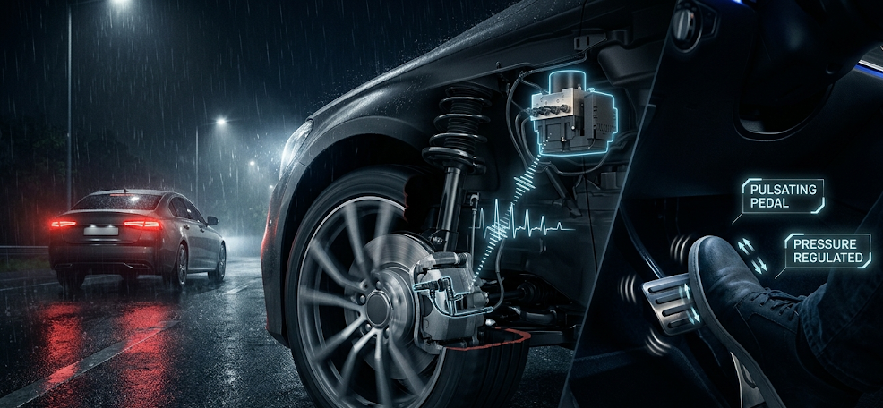
- ASIL-D Subsystems (Zero-Tolerance Failure): Brake-by-wire modulators, Electronic Stability Control (ESC), Electric Power Steering (EPS), and High-Voltage Battery Disconnect Units (BDU). Mandates dual lockstep microcontroller cores, redundant hardware power feeds, and automated failure detection within 10 to 20 milliseconds.
- ASIL-C Subsystems: Electric traction motor torque control and transmission electronic shift-by-wire interlocks.
- ASIL-B Subsystems: Adaptive cruise control (ACC), lane departure warning, and active suspension dampening.
Global Emissions Regulatory Roadmaps: EPA Tier 3, Euro 6d and Euro 7
Internal combustion engines, direct injection fuel systems, and hybrid powertrains are subjected to continuously tightening exhaust emissions legislation. Under Euro 6d-ISC-FCM and forthcoming Euro 7 standards, vehicles must prove real-world emissions compliance on public highways using portable emissions measurement systems (PEMS) across ambient temperatures from -10°C to +38°C:
- Nitrogen Oxides ($NO_x$): Limited to less than 60 mg/km (gasoline) and 80 mg/km (diesel) through combined Selective Catalytic Reduction (SCR) with AdBlue urea injection and cooled low-pressure EGR loops.
- Solid Particle Number ($PN_{10}$): The regulatory measurement threshold has been tightened from 23 nanometers down to 10 nanometers, mandating wall-flow Gasoline Particulate Filters (GPF) across all turbocharged GDI engines.
- On-Board Fuel Consumption Monitoring (OBFCM): Standardized telemetry logging real-world lifetime fuel and electrical energy consumption directly within the engine ECU for regulatory transparency.
By anchoring design methodologies to these internationally recognized SAE, ISO, and UNECE standards, automotive engineers and diagnostic practitioners ensure that mechanical components deliver peak operational reliability, environmental compliance, and life-saving occupant protection.
Combustion Chamber Fluid Mechanics, Tumble Flow and Thermodynamic Boundary Layers
In the thermodynamic optimization of internal combustion engines, the geometric architecture of the cylinder head combustion roof exerts direct control over flame propagation speed and thermal heat losses. Modern direct-injection four-valve pent-roof combustion chambers are engineered to generate high-velocity Intake Tumble Flow—a coherent barrel-shaped vortex of air rotating perpendicularly to the cylinder axis.
As the piston accelerates upward on the compression stroke toward Top Dead Center, geometric squish pads on the piston crown compress this large tumble vortex, breaking it down into a cascade of fine, high-intensity microscopic turbulent eddies. This microscopic turbulence increases the Turbulent Flame Speed ($u_t$) by a factor of four compared to laminar flame speeds ($u_l$), completing combustion in fewer crank angle degrees and allowing significant spark retard reduction.
Piston Ring Tribology and Blow-by Hermetic Gas Sealing
Reciprocating pistons rely on three precision-engineered piston rings running inside plateau-honed cylinder liners to maintain gas hermetic sealing while controlling oil consumption: the Top Compression Ring, the Second Scraper Ring, and the Three-Piece Oil Control Ring. The top compression ring—manufactured from nodular cast iron or stainless steel with physical vapor deposition (PVD) diamond-like carbon (DLC) coatings—utilizes cylinder gas combustion pressure entering behind the ring groove to force the ring face tightly against the cylinder wall. Minimizing blow-by past the ring gaps to under 15 to 25 liters per minute prevents crankcase pressurization, preserves oil quality, and eliminates hydrocarbon emissions leakage.

Lead Automotive Research Engineer, Master ASE Certified Diagnostic Specialist, and powertrain dynamics consultant with over 18 years of experience in internal combustion thermodynamics, electric vehicle architectures, and chassis control systems.